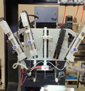
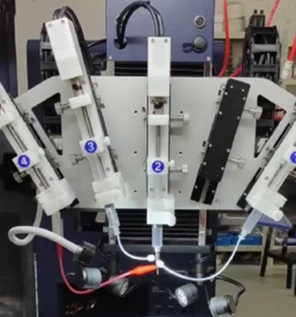
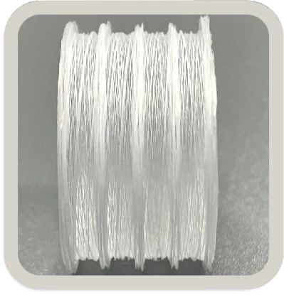
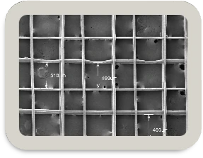
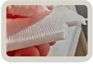
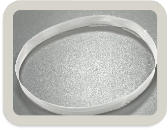
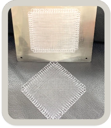
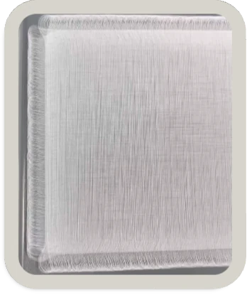
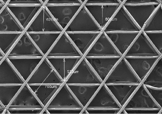
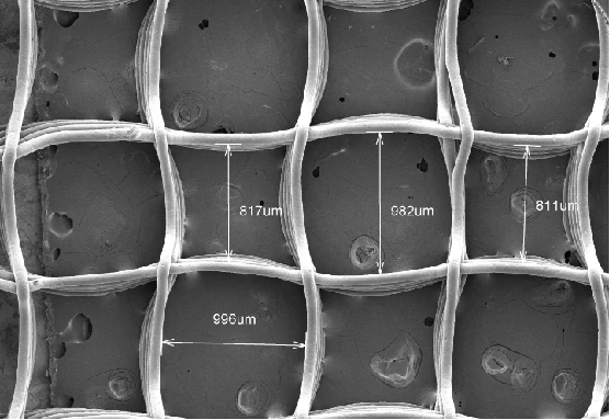
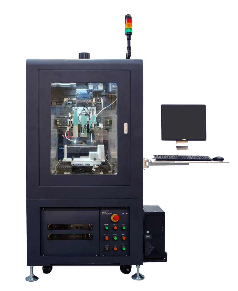
Combine melt electrowriting, near-field solution direct writing and high-voltage electrospinning on one configurable platform. Study ordered fiber scaffolds and nanofiber membranes with coordinated motion, material delivery and process control.
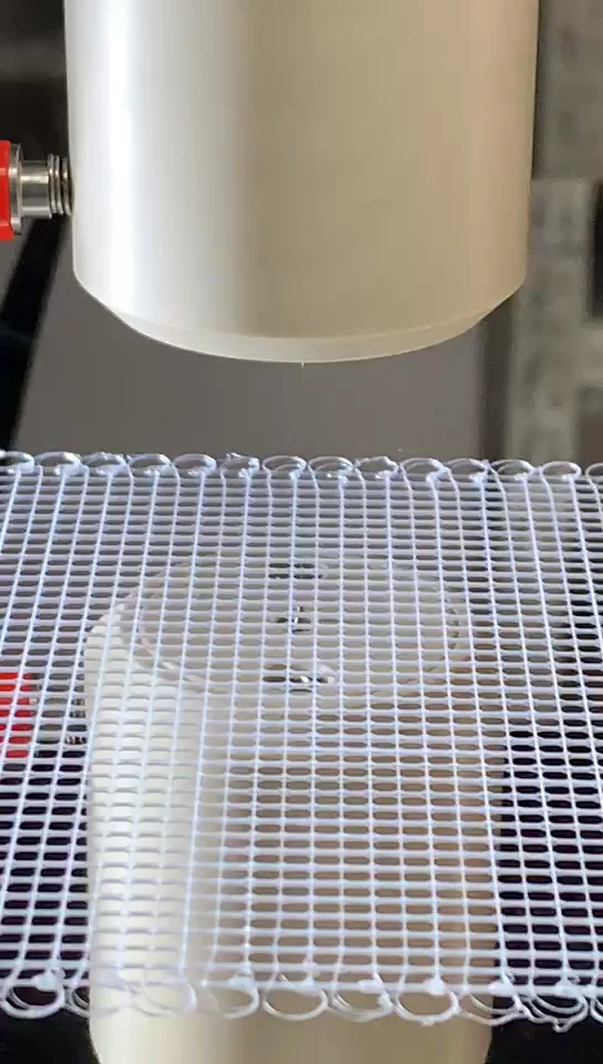
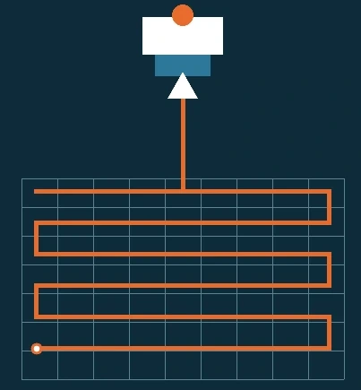
Direct writing places a continuous micro- or nanofiber along a controlled toolpath to build ordered two- or three-dimensional structures. The same coordinate system supports changes between material systems, deposition geometries and processing modes.
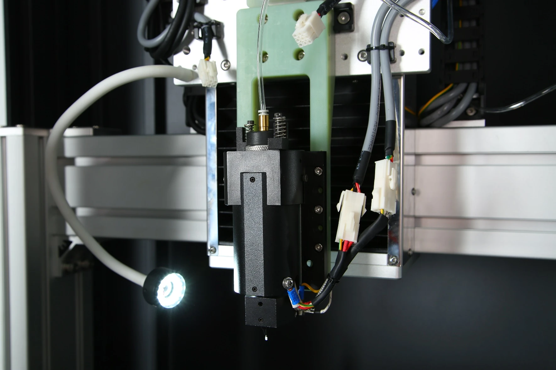
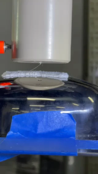
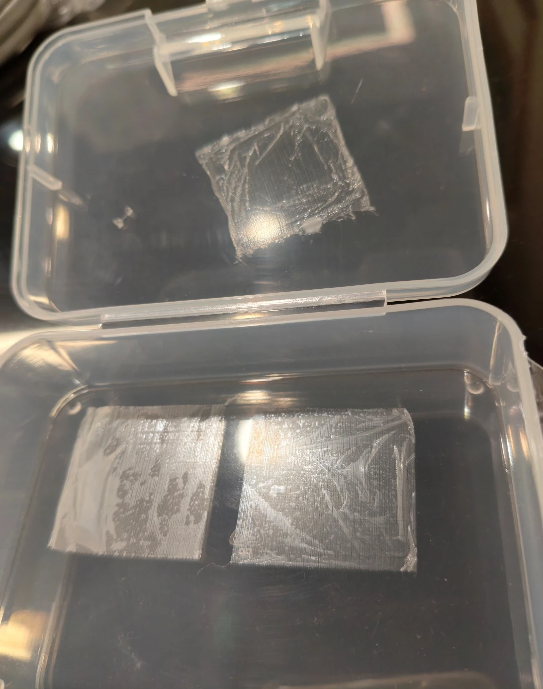
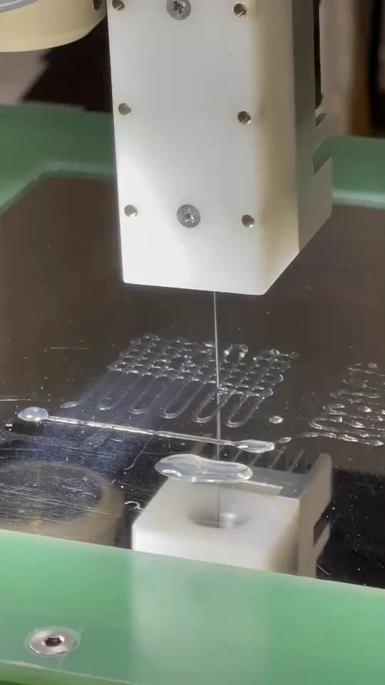
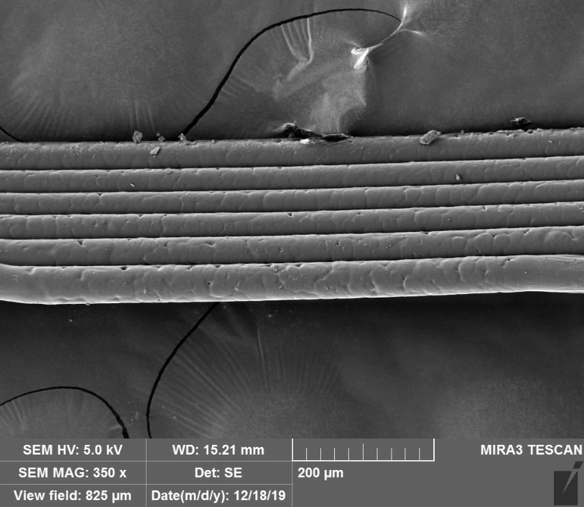
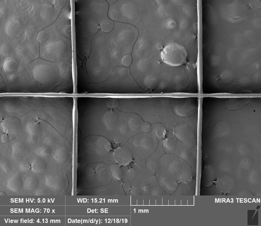
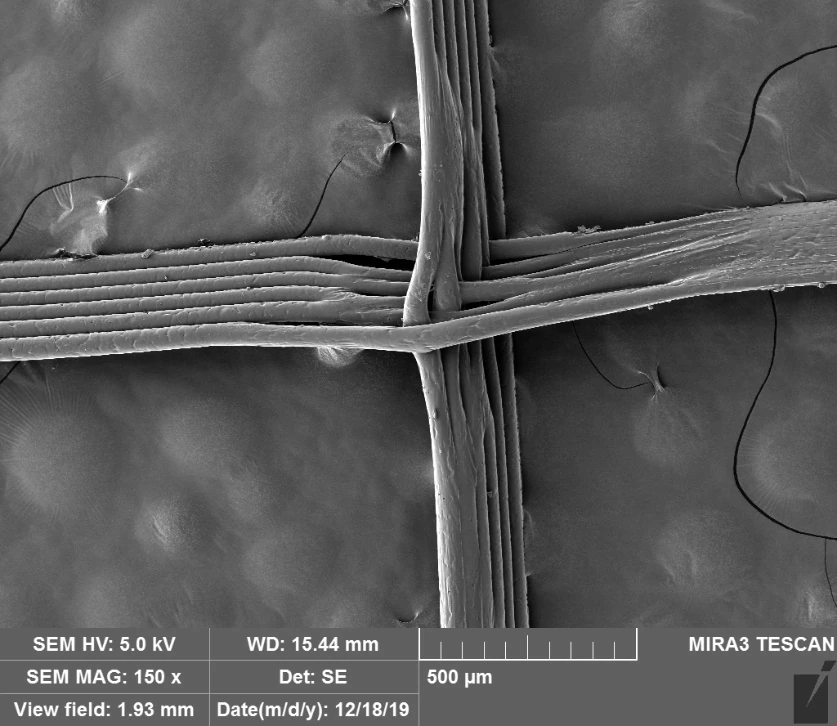
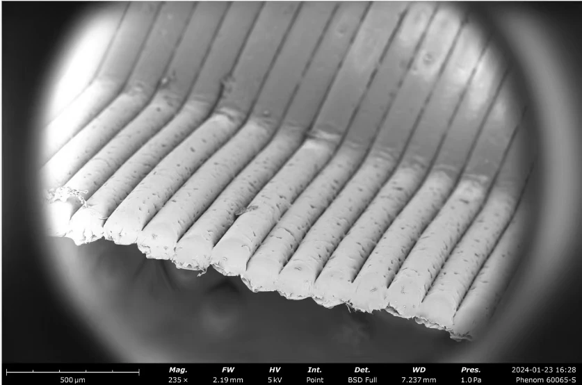
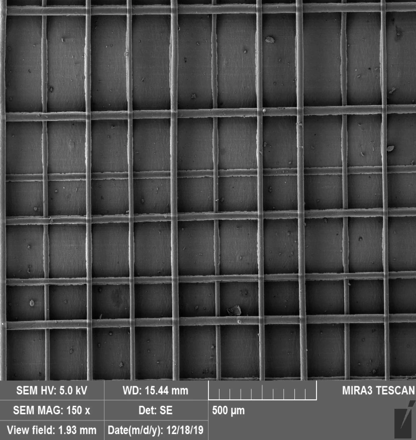
A high-voltage field draws the polymer melt as the stage places fibers along programmed paths. Solvent-free processing supports ordered 2D/3D scaffolds, with a stated fiber-diameter range of 1–100 μm.
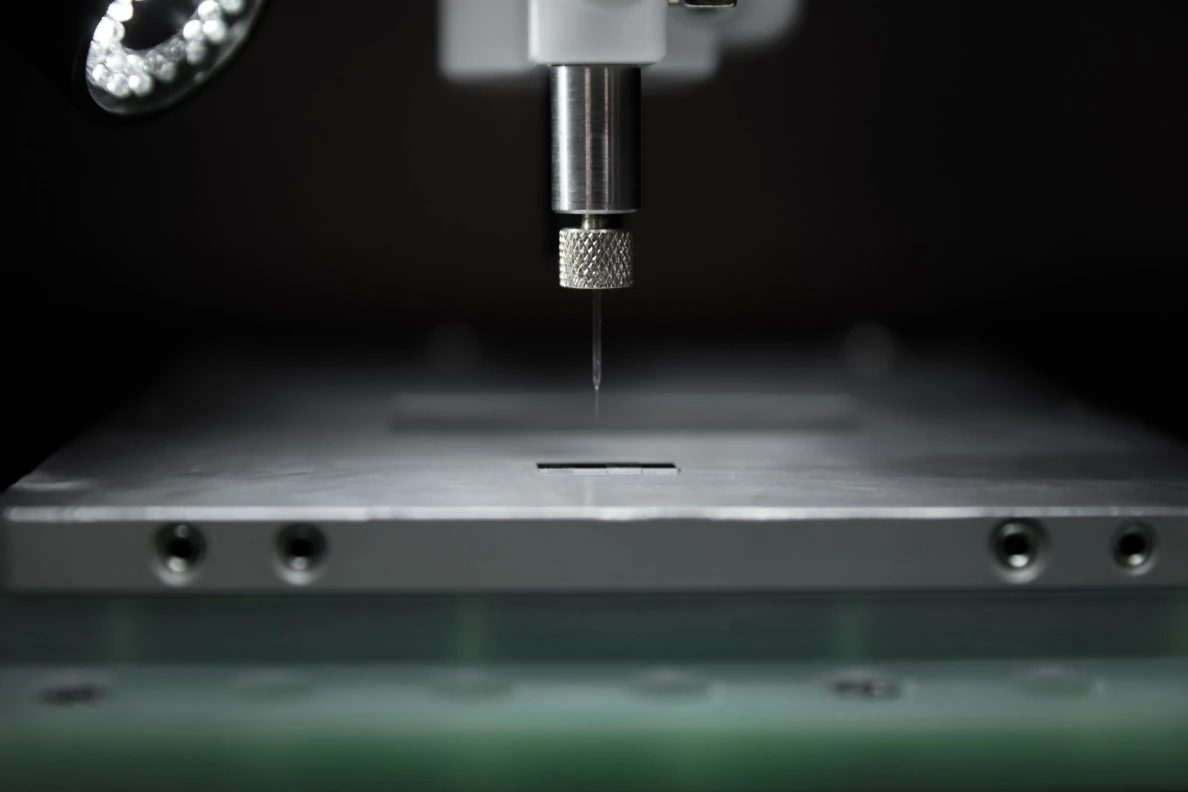
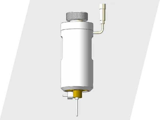
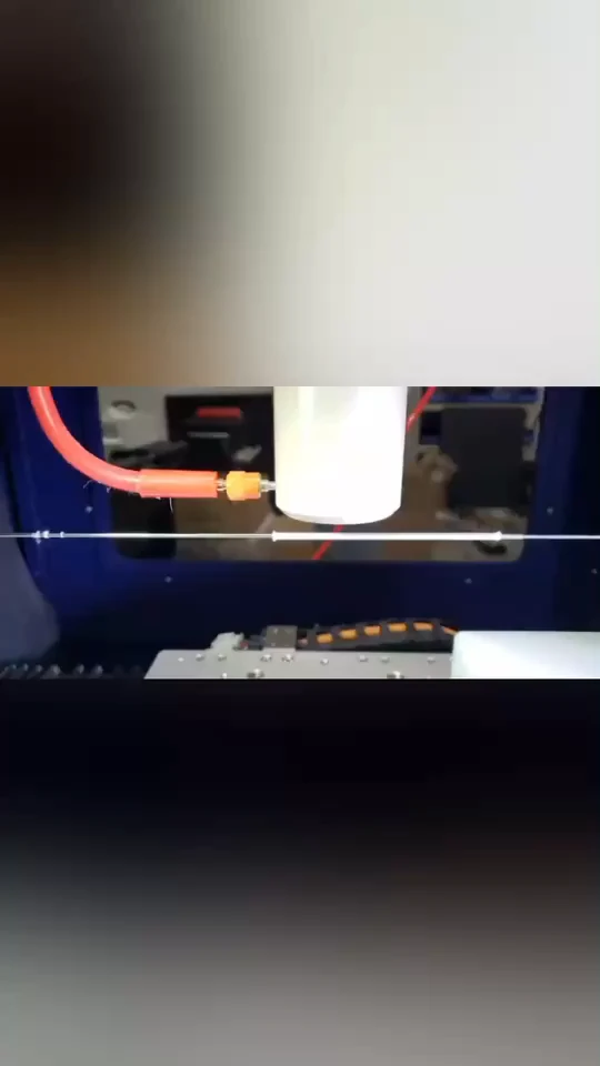
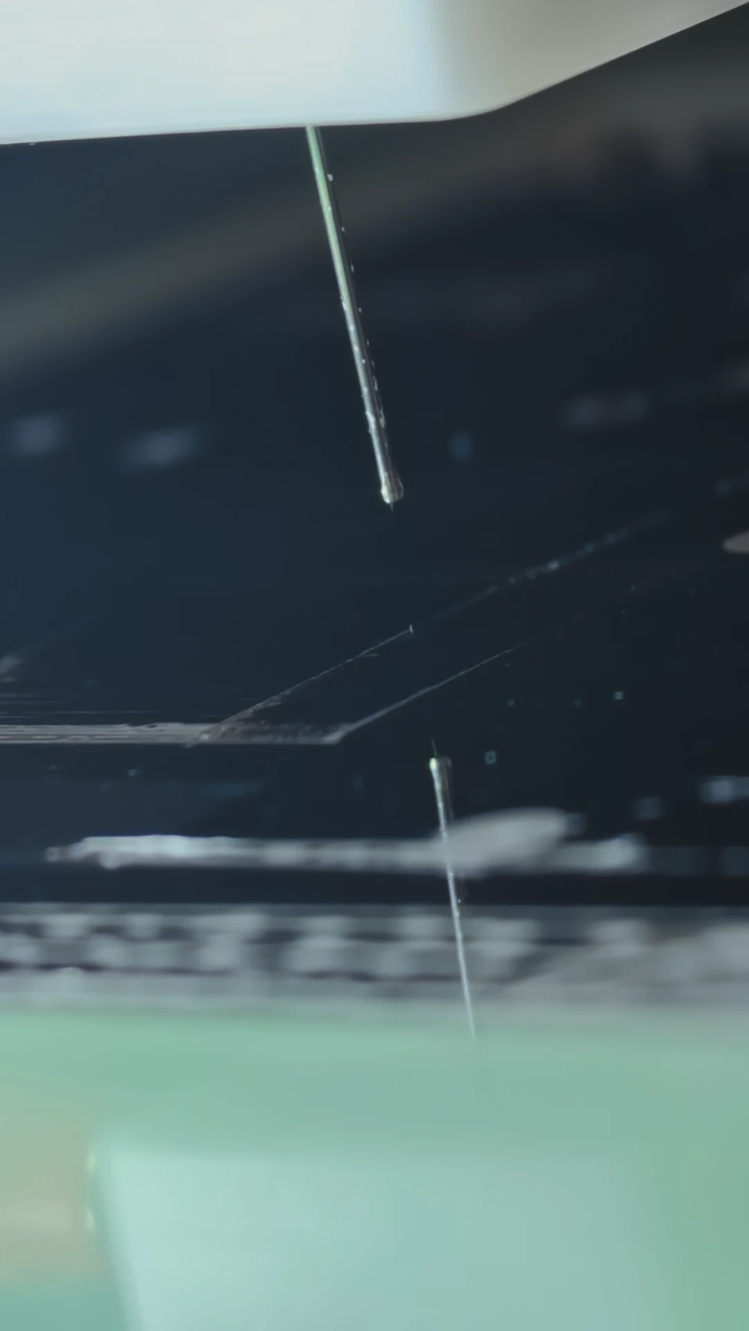
Write continuous lines and curves from solution or composite material systems. Glass needles span 1–45 μm in diameter, with liquid feeding from 0.01 to 99.9 mL/h.
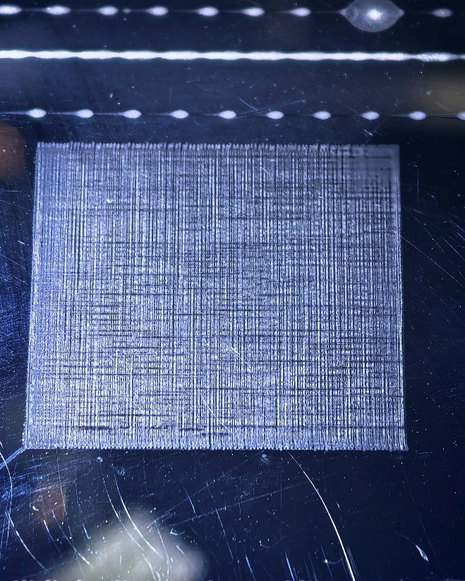
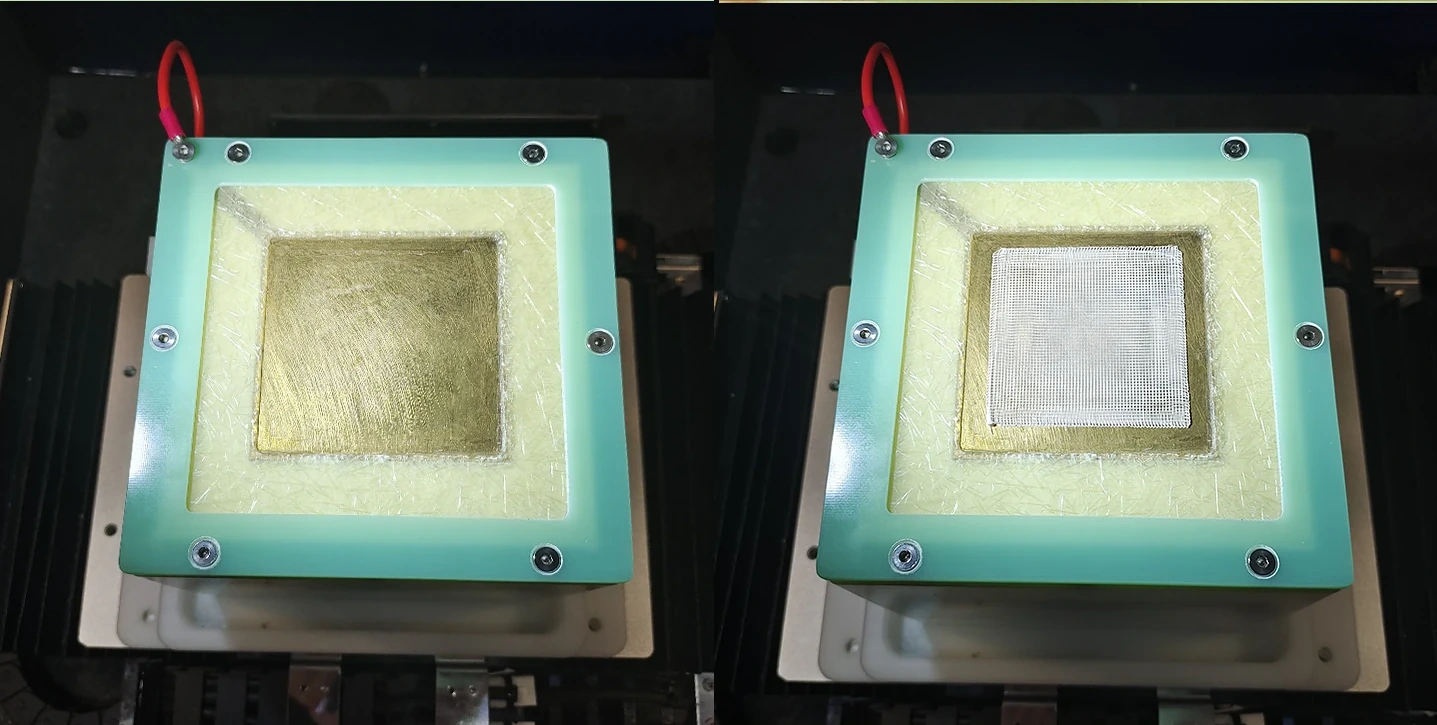
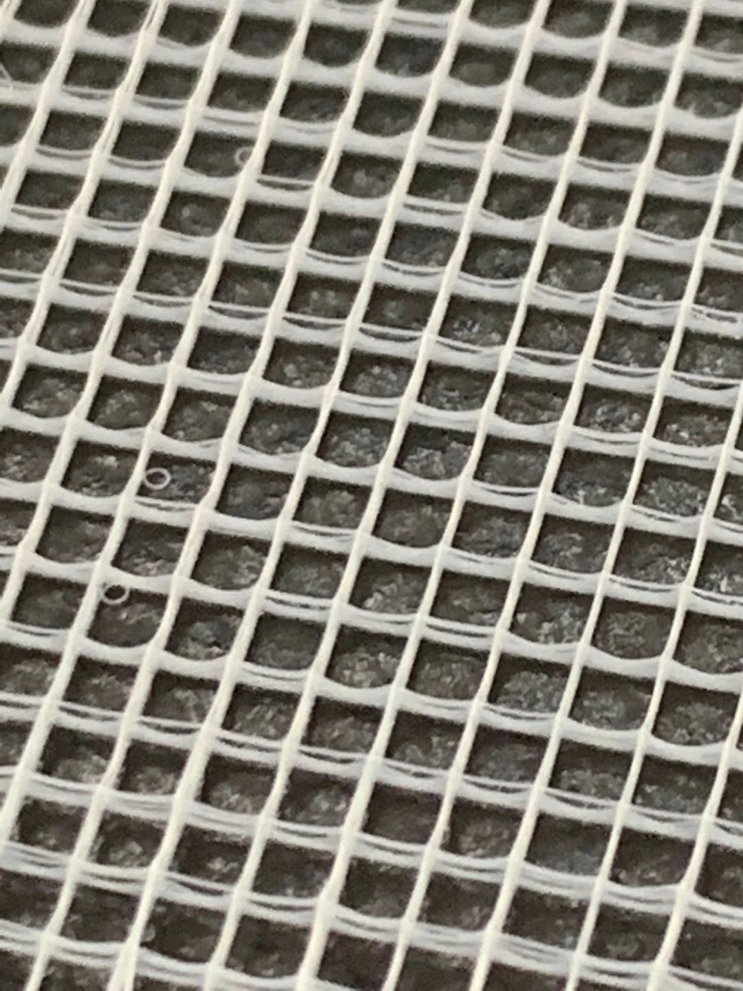
Produce dense nano- and microfiber membranes with single, side-by-side, coaxial or triaxial spinnerets. Choose the collector and channel arrangement for the required fiber architecture.
Materials, structures and research applications
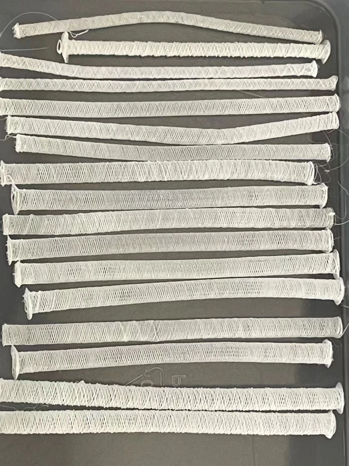
Modules cover low-temperature biomaterials through high-temperature engineering polymers. Study ordered microfiber scaffolds or random nanofiber membranes on flat, tubular and curved surfaces, including multilayer structures. The platform supports exploratory research, process-window screening and shared research facilities.
Tissue engineering: tendon, cartilage, bone, nerve and muscle scaffolds.
Tubular structures: vascular, tracheal and conduit research.
Functional composites: piezoelectric, conductive, magnetic and particle-reinforced systems.
Wound care and drug delivery: porous patches and loaded structures.
Soft devices: liquid-crystal elastomers and programmable actuation.
Hybrid biomanufacturing: hydrogels, cells, electrospinning and 3D printing.
Application suitability and sample performance depend on the material, geometry, processing environment, post-processing and validation.
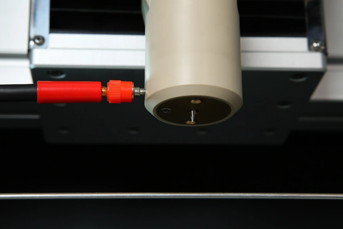
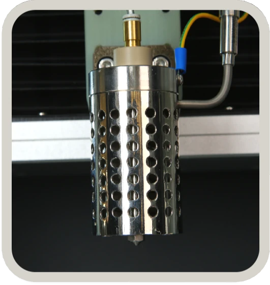
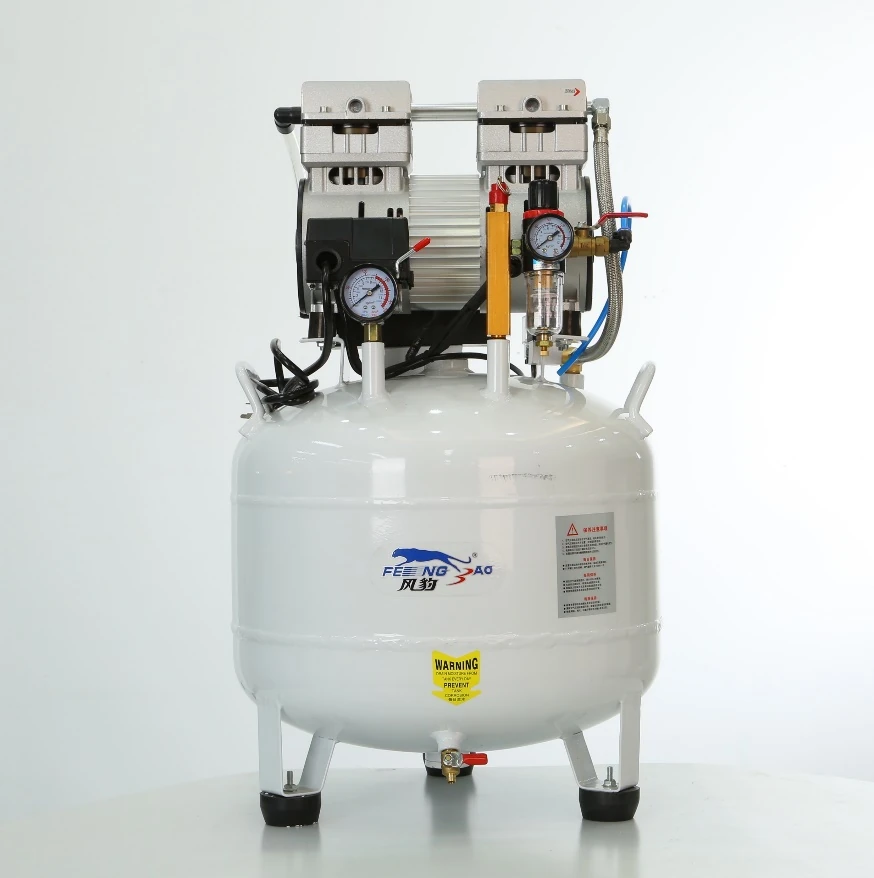
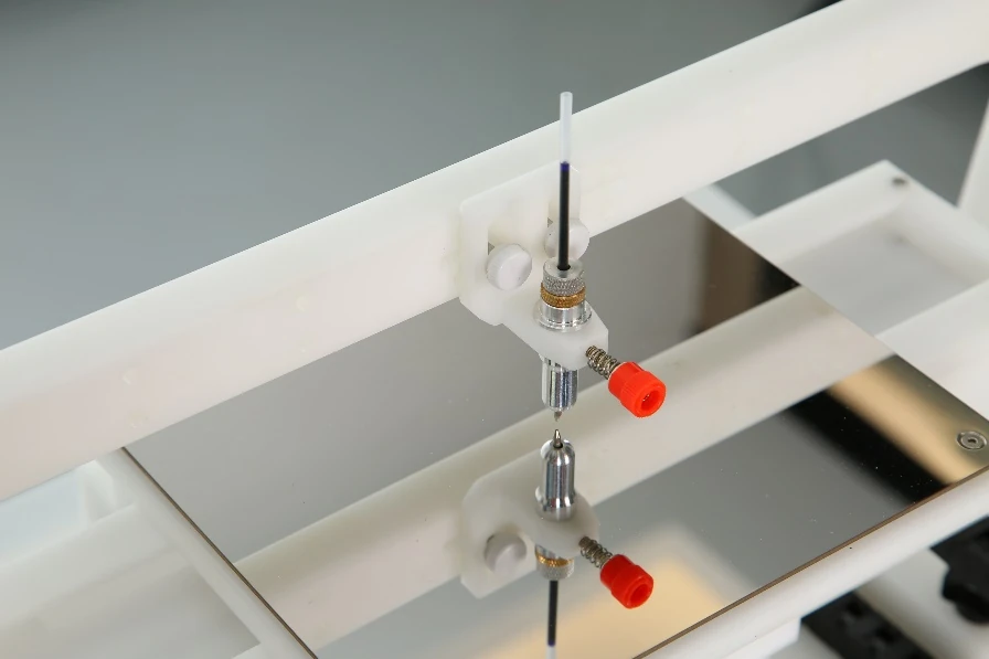
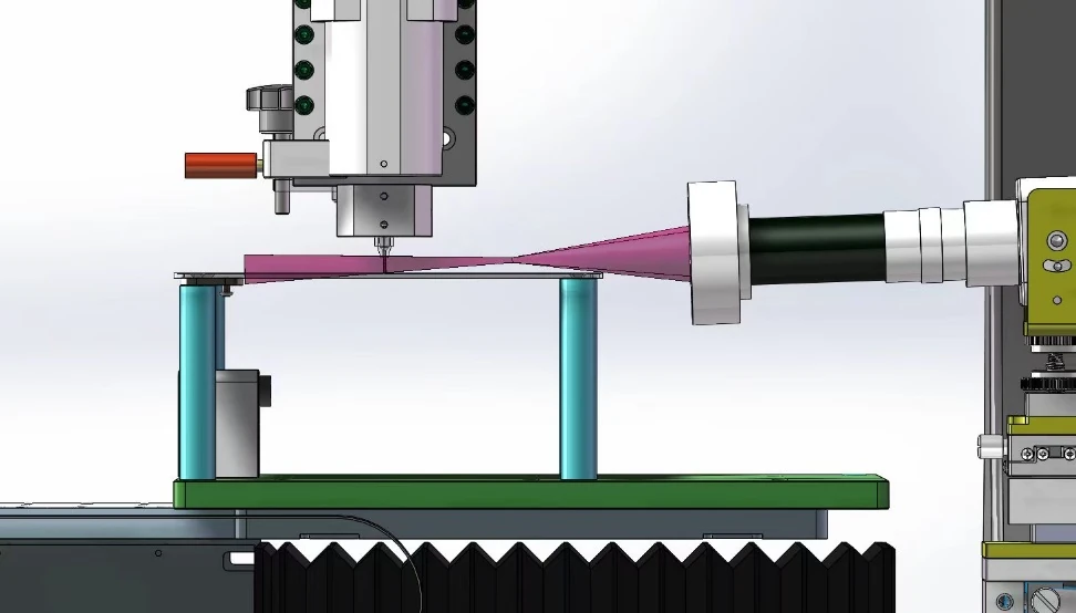
A coaxial hot-air shield provides 25–120°C outer-zone heating for high-temperature heads, reducing ambient effects and premature solidification. Pneumatic feed offers three pressure resolutions and can use an air pump or inert gas. Gas and cylinder arrangements follow the selected configuration.
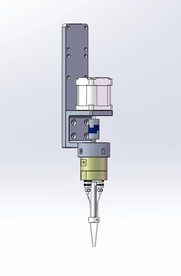
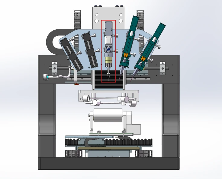
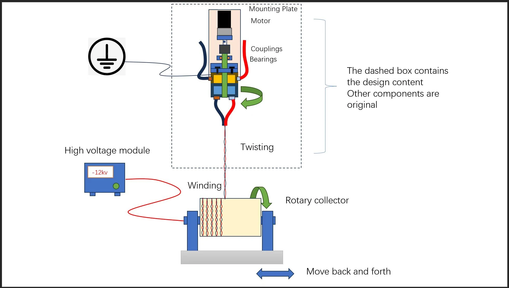
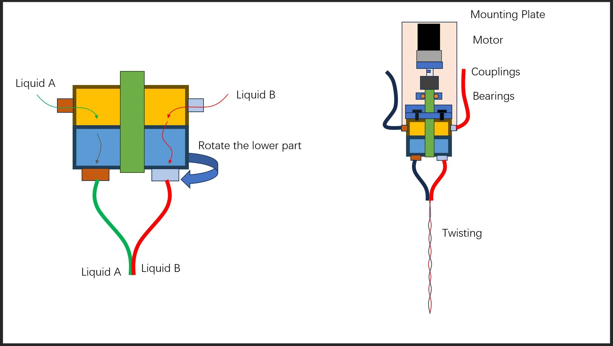
This optional head combines two solution streams with in-line twisting to study composite and multicomponent fibers. Rotational speed is digitally adjustable from 1 to 100 rpm.
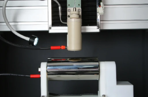
This mode uses no high voltage. Adjustable pneumatic extrusion deposits photocurable material along the programmed path while four UV lamps cure it in situ. UV wavelength, power and lamp format can be configured.
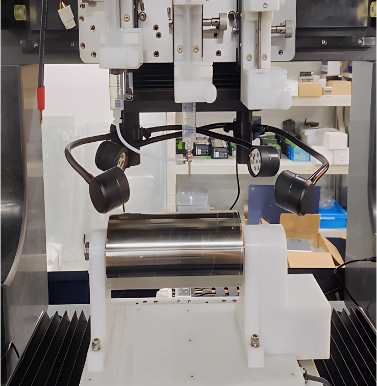
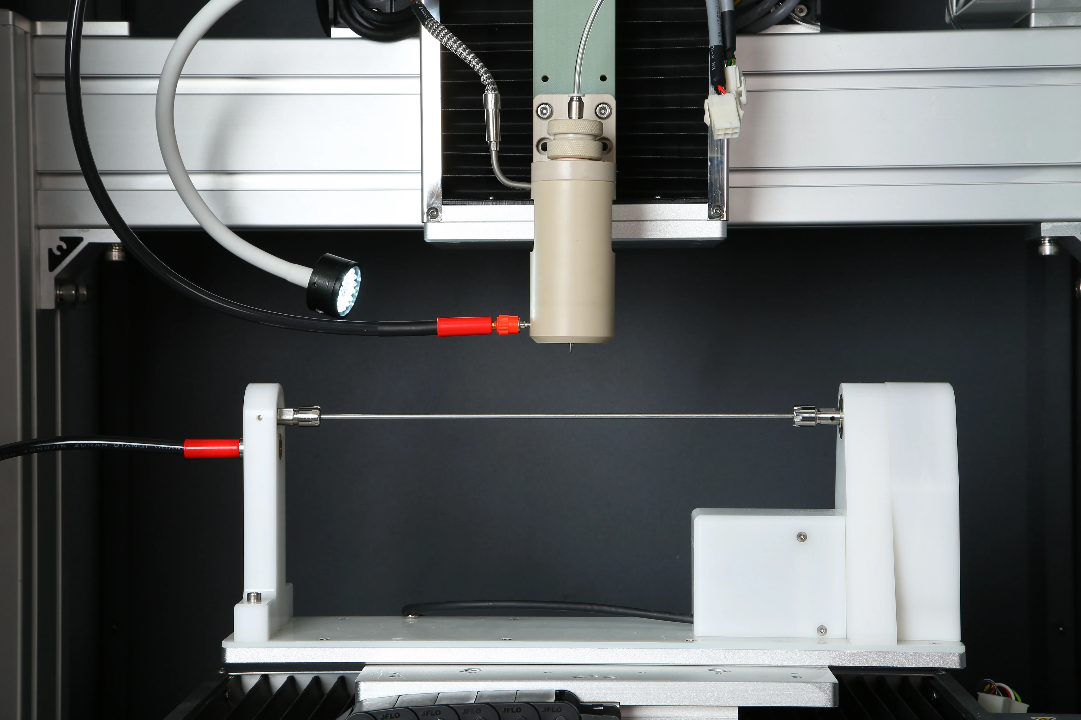
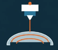
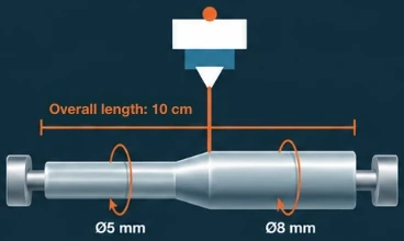
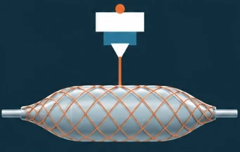
Optional surface scanning and following maintain the working distance while compensating the toolpath for hemispherical surfaces, tapered mandrels and balloon or tubular geometries. The tapered example shown is 10 cm long, with 5 cm sections of Ø5 mm and Ø8 mm.
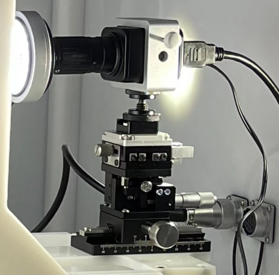
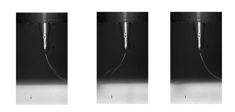
Adjustable focus helps document fiber drawing and jet behavior. Camera views and the observation arrangement support review of the printing process.
04
Motion & software
Precision motion architecture
A granite base supports X/Y linear motors and a Z servo drive. The upper X and lower Y axes each travel more than 180 mm at speeds up to 200 mm/s, with positioning accuracy of ±2 μm. Z travel exceeds 80 mm, with speeds up to 50 mm/s.
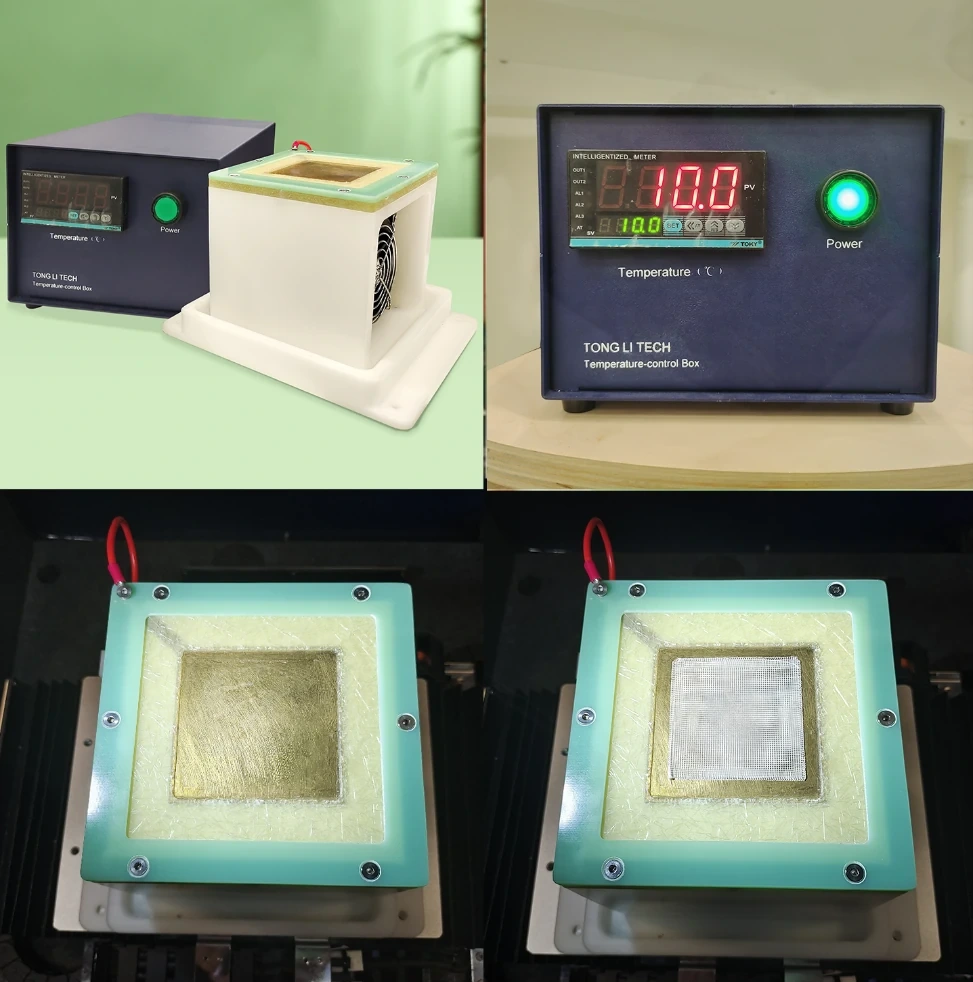
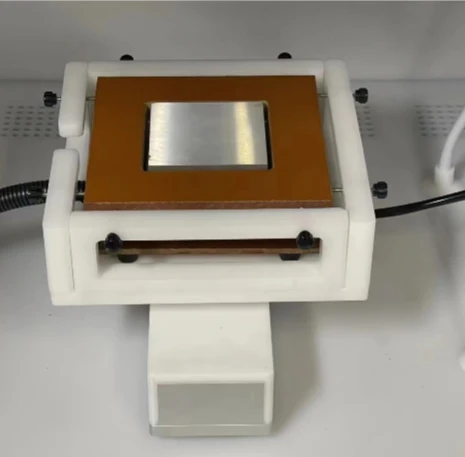
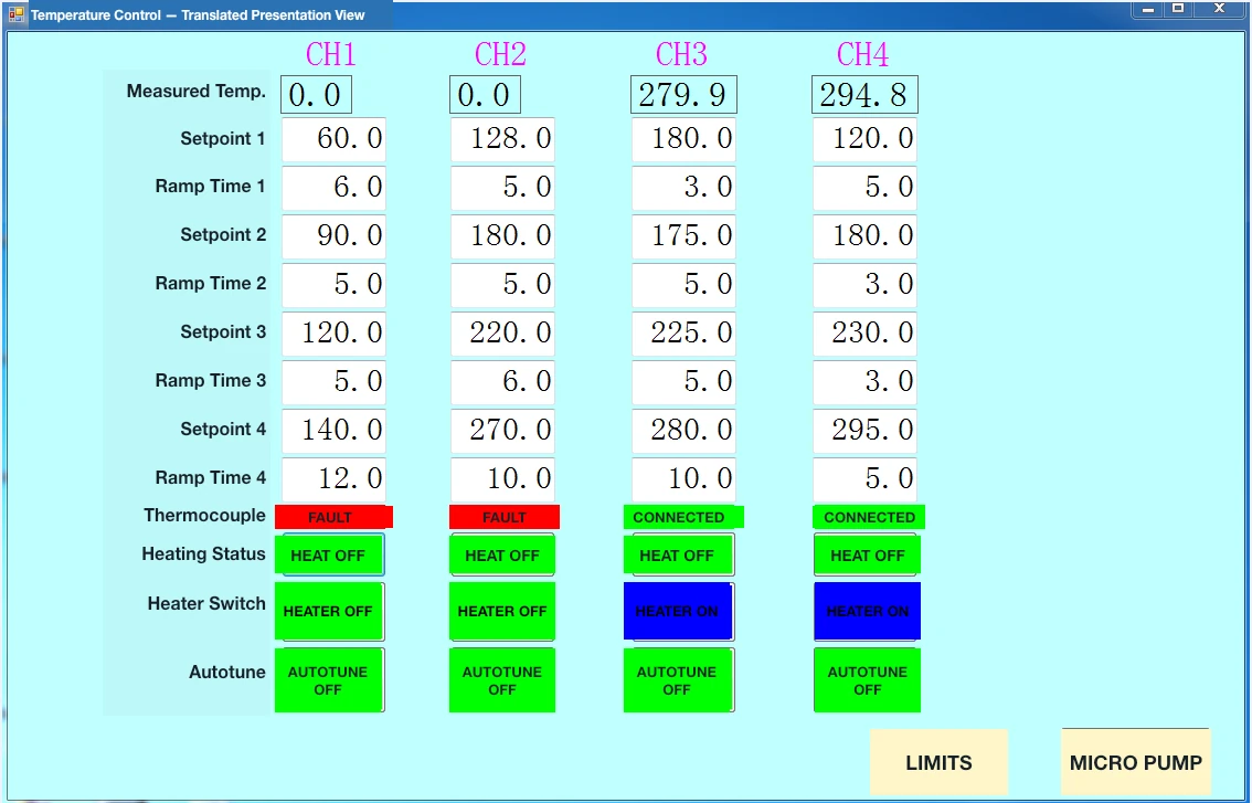
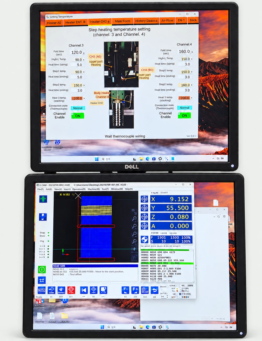
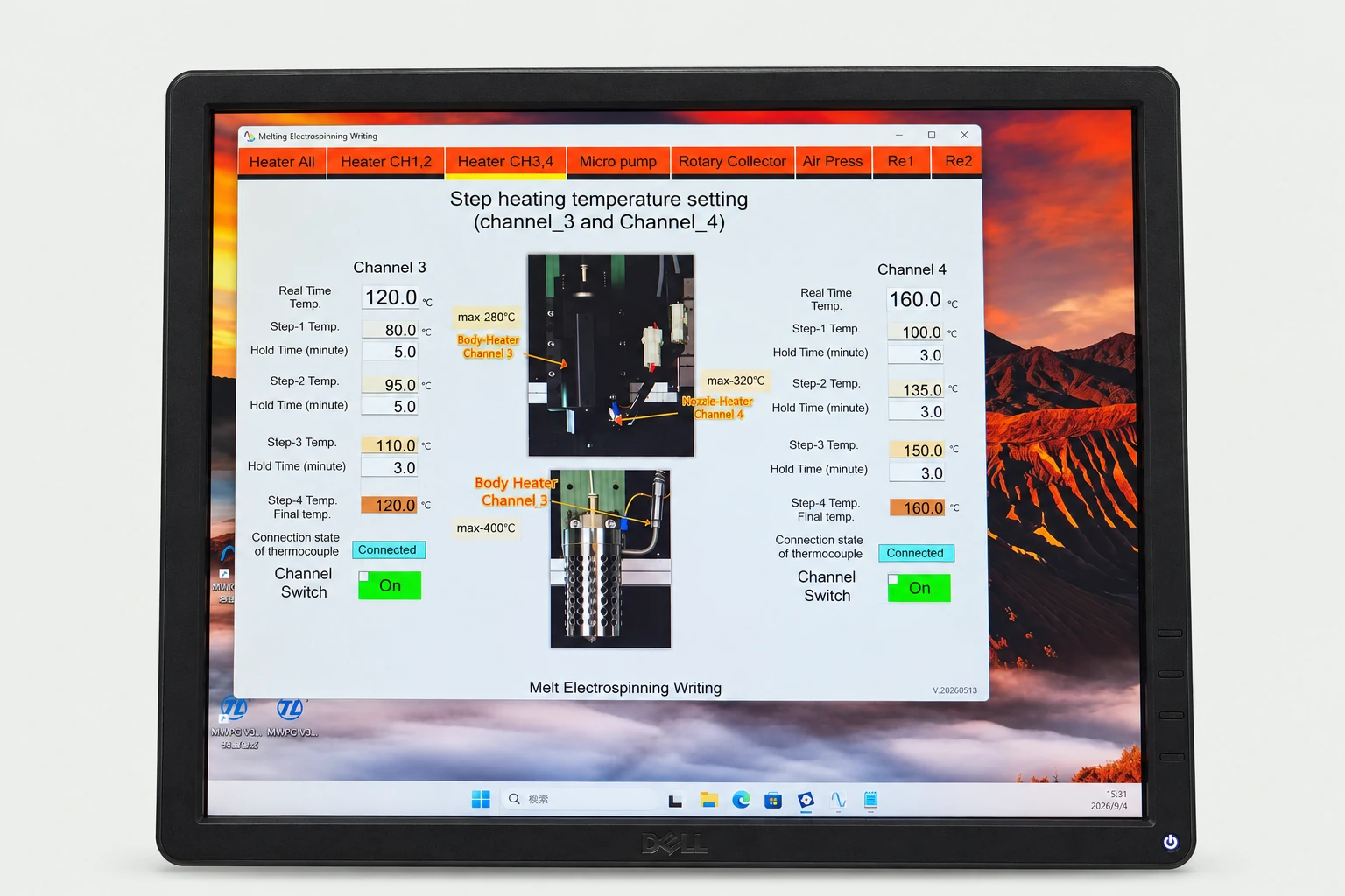
Independent channels coordinate heating and collector temperature. Four-stage temperature ramps with individual dwell times help control the material’s thermal history. The software shows thermocouple status and provides individual output switching.
CH 01: ambient–150°C; four-stage temperature ramp
CH 02: collector-plate temperature control
CH 03: ambient–400°C
CH 04: ambient–300°C
Pressure and dual-channel liquid feed
Set inlet pressure on the touchscreen with selectable resolutions of 0.1, 0.01 or 0.001 MPa. Dual-channel liquid feeding covers 0.01–99.9 mL/h and accepts 10 mL or 20 mL syringes.
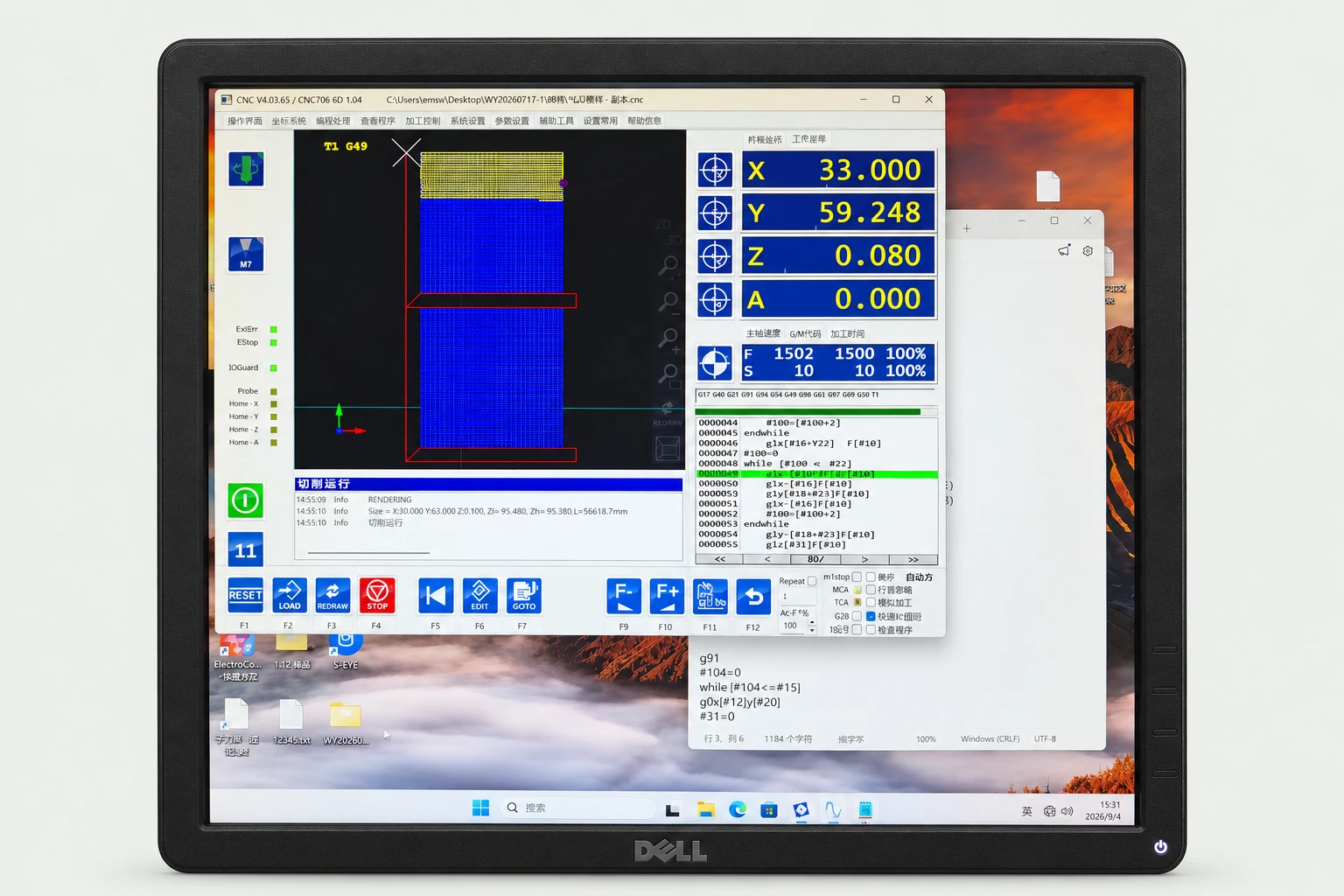
Thermal and process settings remain visible alongside motion execution. View the toolpath, X/Y/Z/A positions and feed status while running G-code line by line. The control platform uses EdingCNC and CNC4.03 software.
Import 2D and 2.5D CAD geometry or 3D STL models. Convert photos, scans, sketches and digital drawings into paths. Generate parametric grids without a CAD model, then edit paths, speeds and print parameters. Assign speeds by geometry, region or segment before generating G-code.
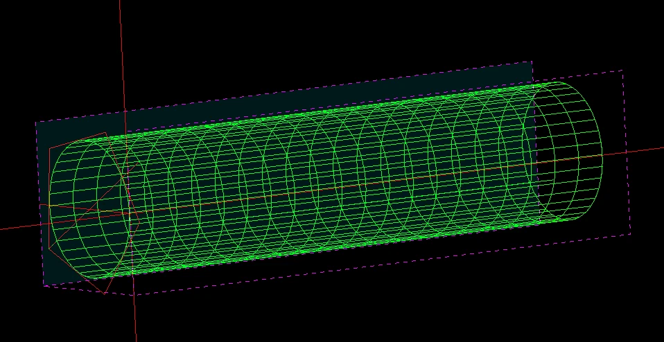
Grid and tubular templates generate geometry from structural and process parameters. Simulate and refine the path before printing. Parameter sweeps run multiple settings and geometries, a warm-up zone stabilizes flow before the target path starts, and stacked geometries can include a separate warm-up at each transition.
01Select grid or tube
02Set structure and process parameters
03Simulate and refine
04Export G-code and print
05
Scaffolds & samples
Tubular scaffold workflow
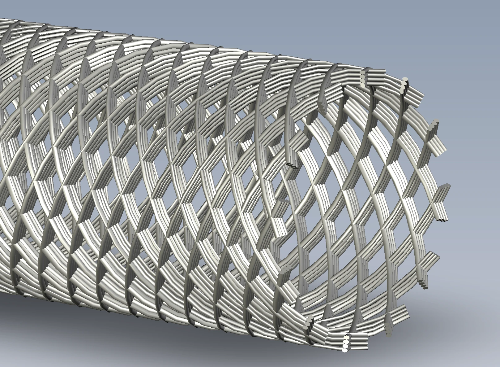
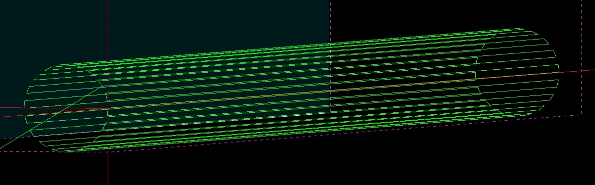
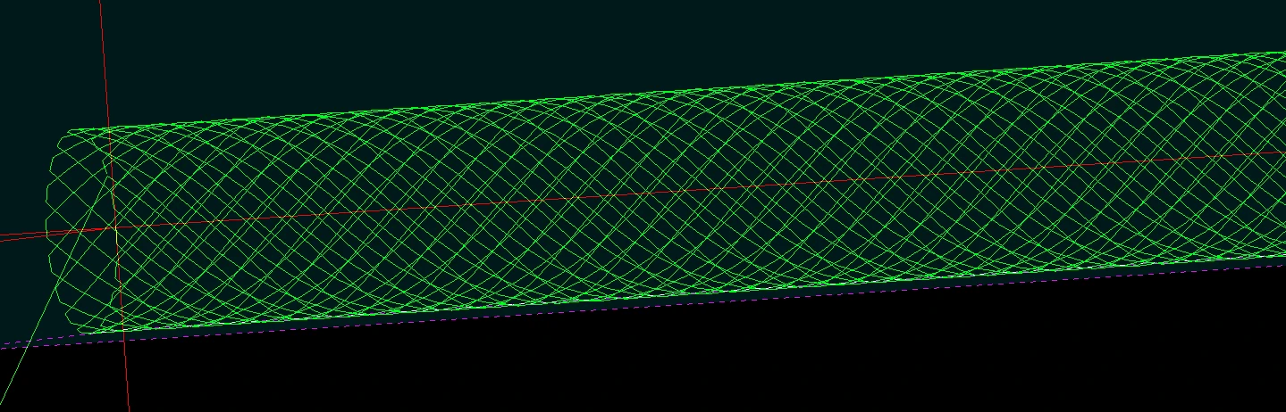
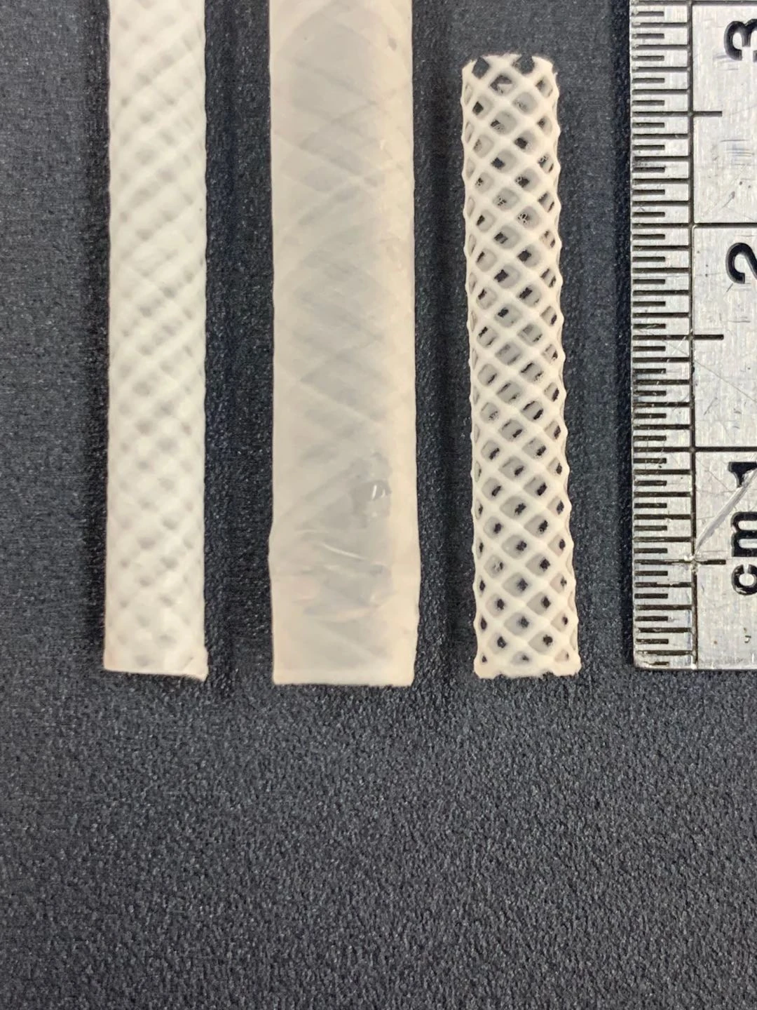
Parametric models generate axial or cross-hatched paths without manual line-by-line drafting. Rotation, fiber angle, spacing and layer count define the scaffold geometry and influence porosity, compliance and mechanical response.
These functions work alongside laboratory risk assessment, material-compatibility review and compliant operating procedures.
Configuration for your material and target structure
Core research platform
Three fiber-processing modes, a precision motion platform, standard printhead and flat-plate collector, control software and safety functions.
Options for the material
Low-, mid- or high-temperature melt heads, inert-gas feeding, a low-temperature hydrogel head and UV curing.
Options for the geometry
Rotating, heated or cooled collectors; curved-surface scanning and following; coaxial, side-by-side or triaxial spinnerets; and a rotating twisting head.
The institute’s Micro/Nano Automation Laboratory describes an integrated electrospinning system combining melt electrowriting, solution near-field electrospinning and high-voltage electrospinning for direct writing and fiber or membrane preparation.
TONGLI identifies this customer system as TL-Trinity; the linked equipment page describes its three processing modes without naming the model.


 Enlarge image ↗