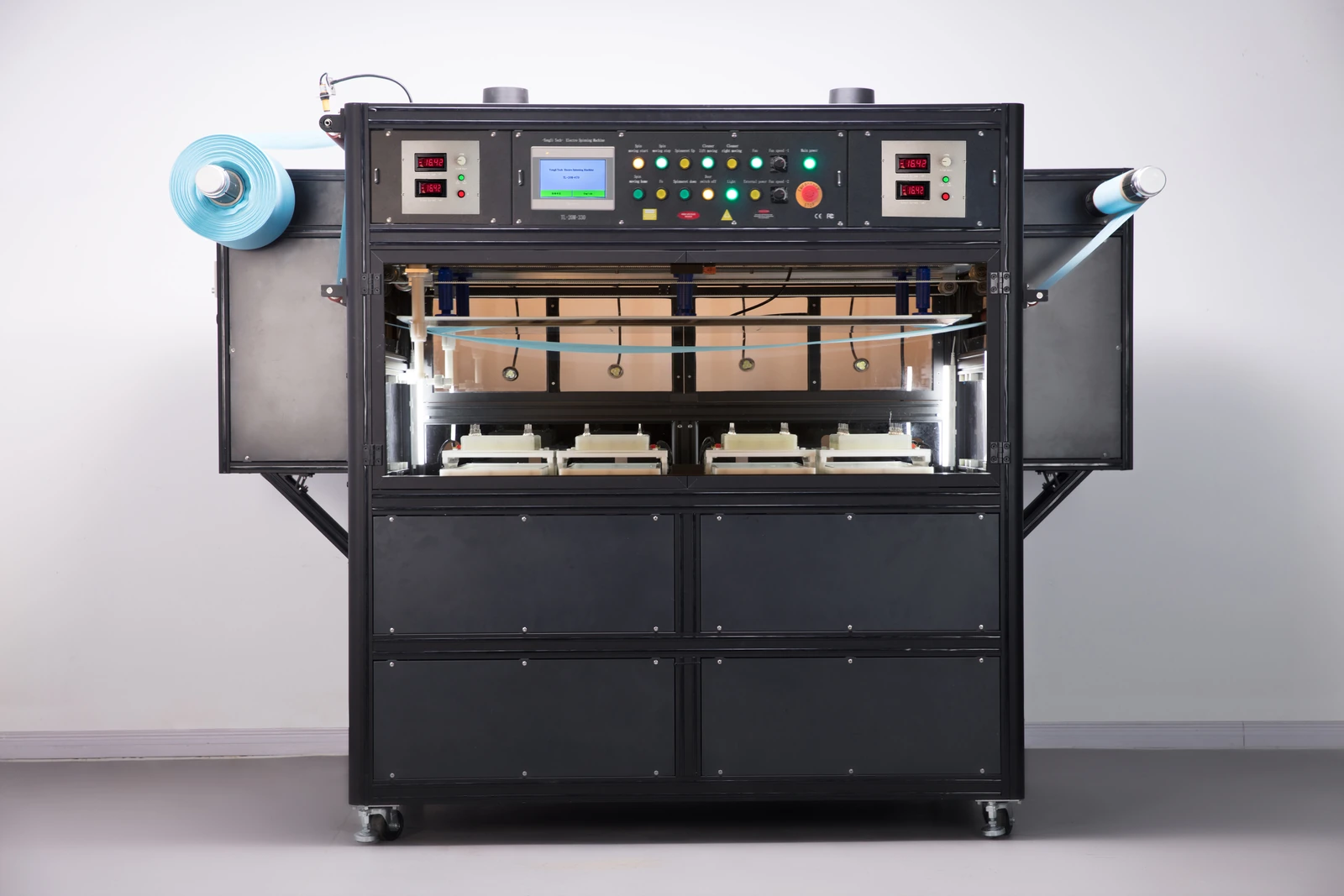
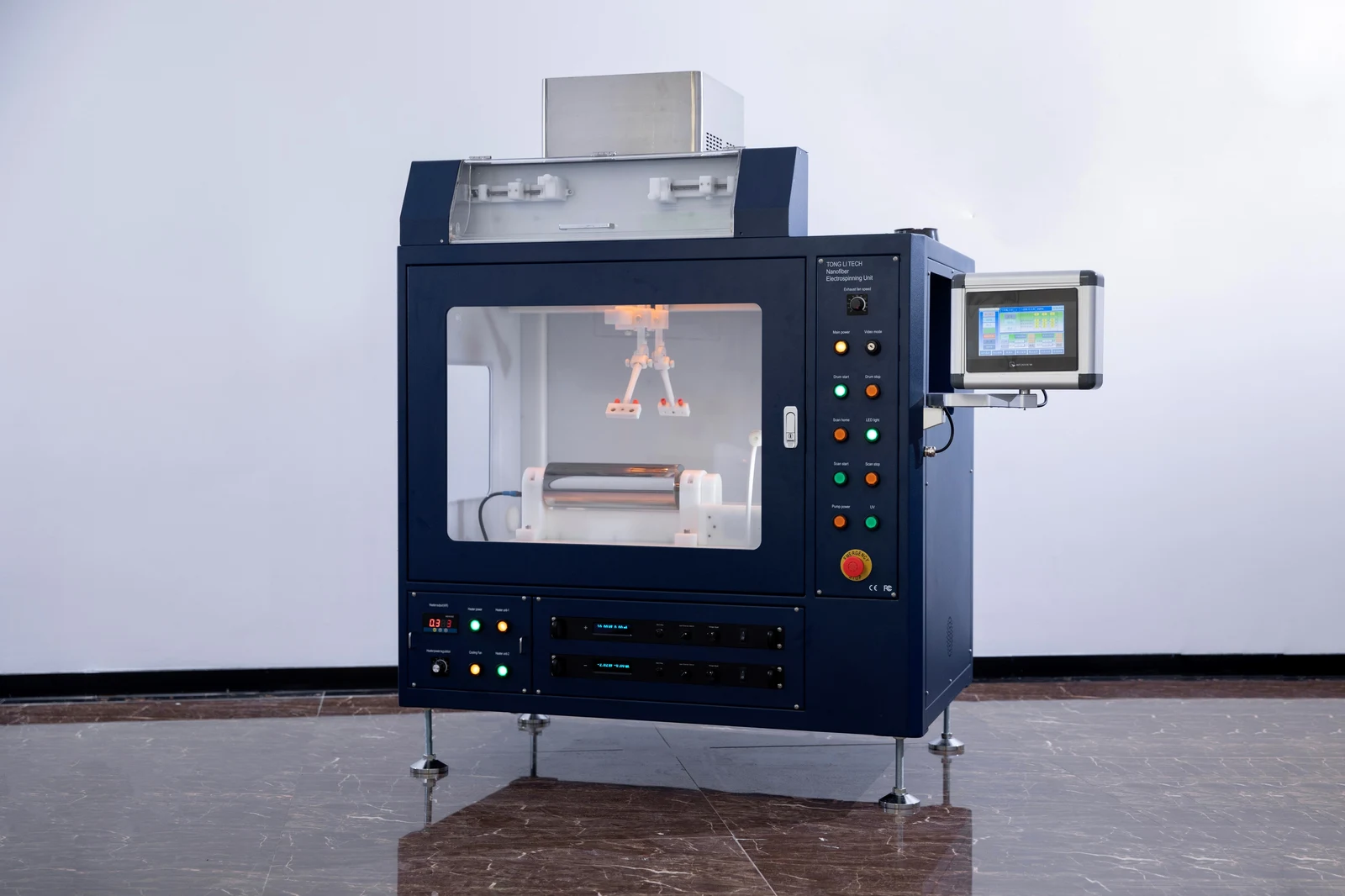
TL-20M-200 / TL-20M-400

TL-20M

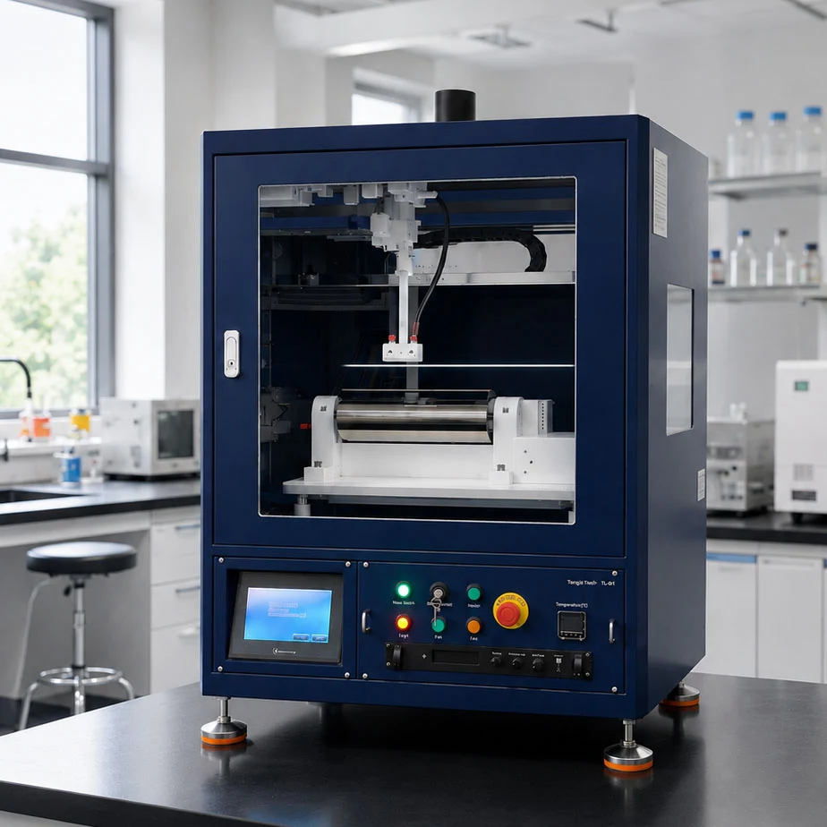
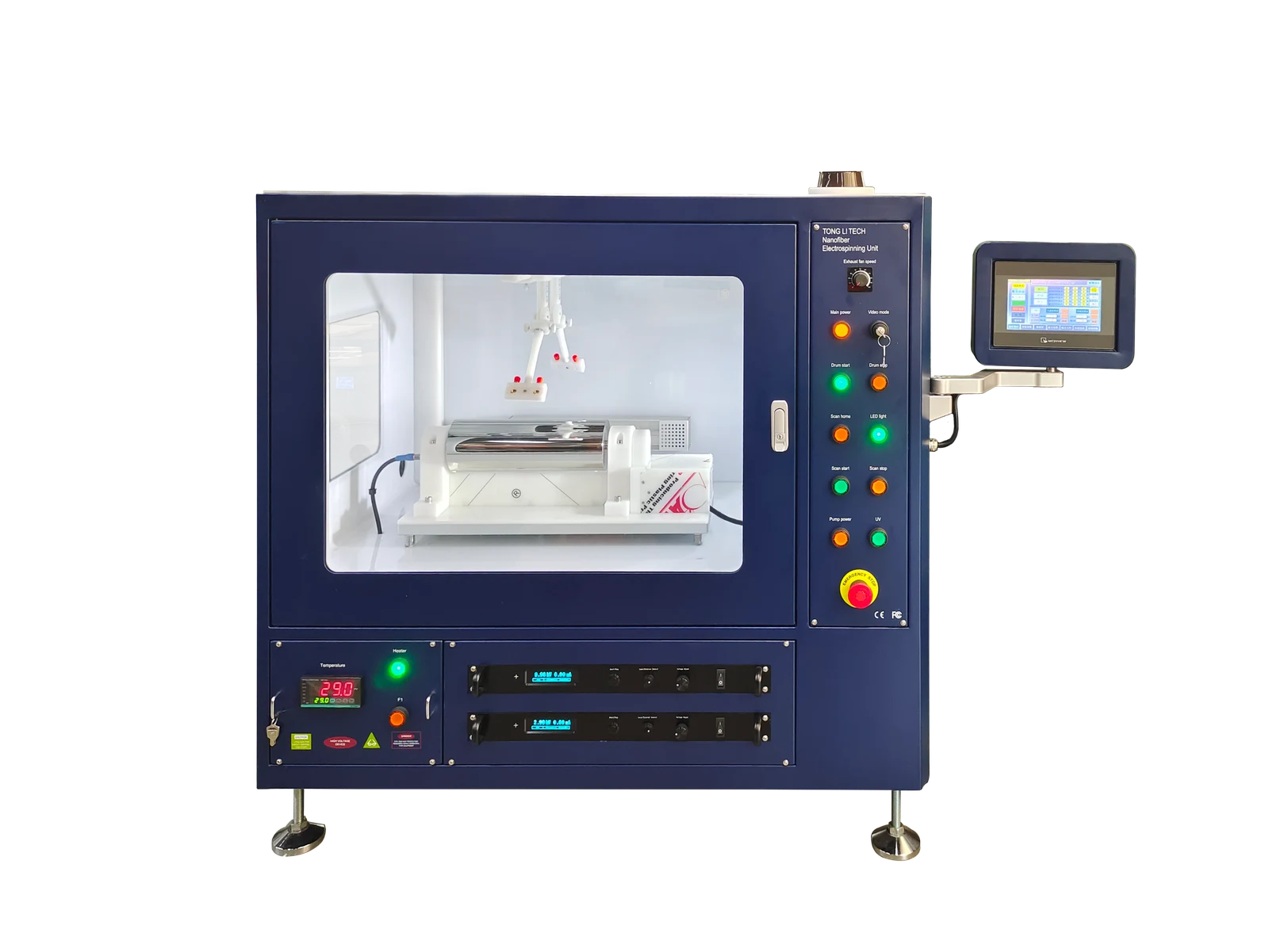
Modular electrospinning for batch production

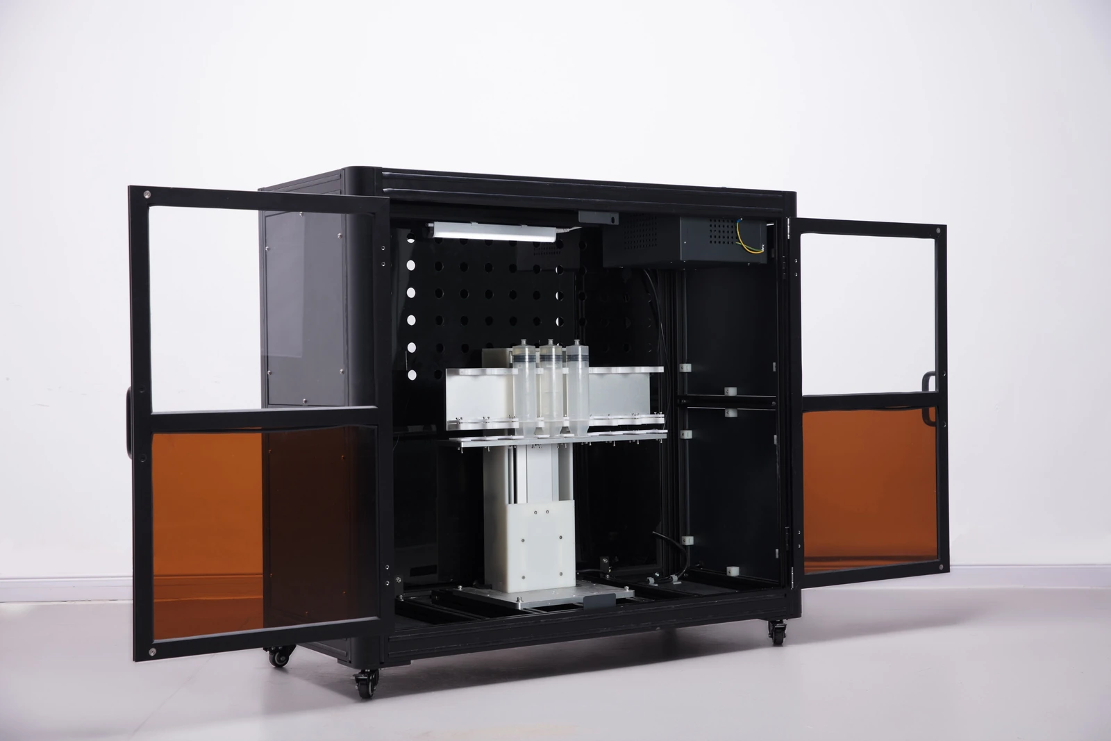
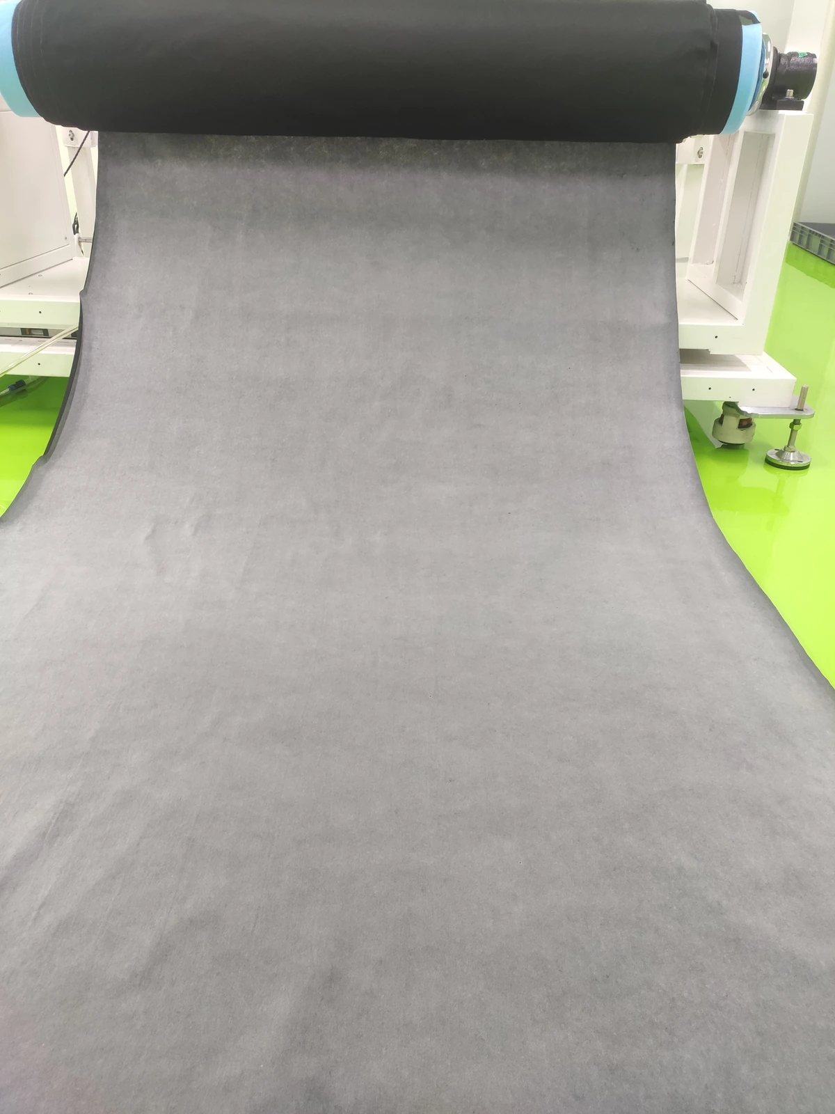
Develop and scale processes for uniform fibrous membranes. Configure the TL-20M with interchangeable spinneret modules, independent solution delivery and either continuous roll collection or fixed-length thick-mat collection.

Download brochure (English PDF)English · PDF · 58.9 MB
01

Platform & models

Uniform deposition at batch-production scale

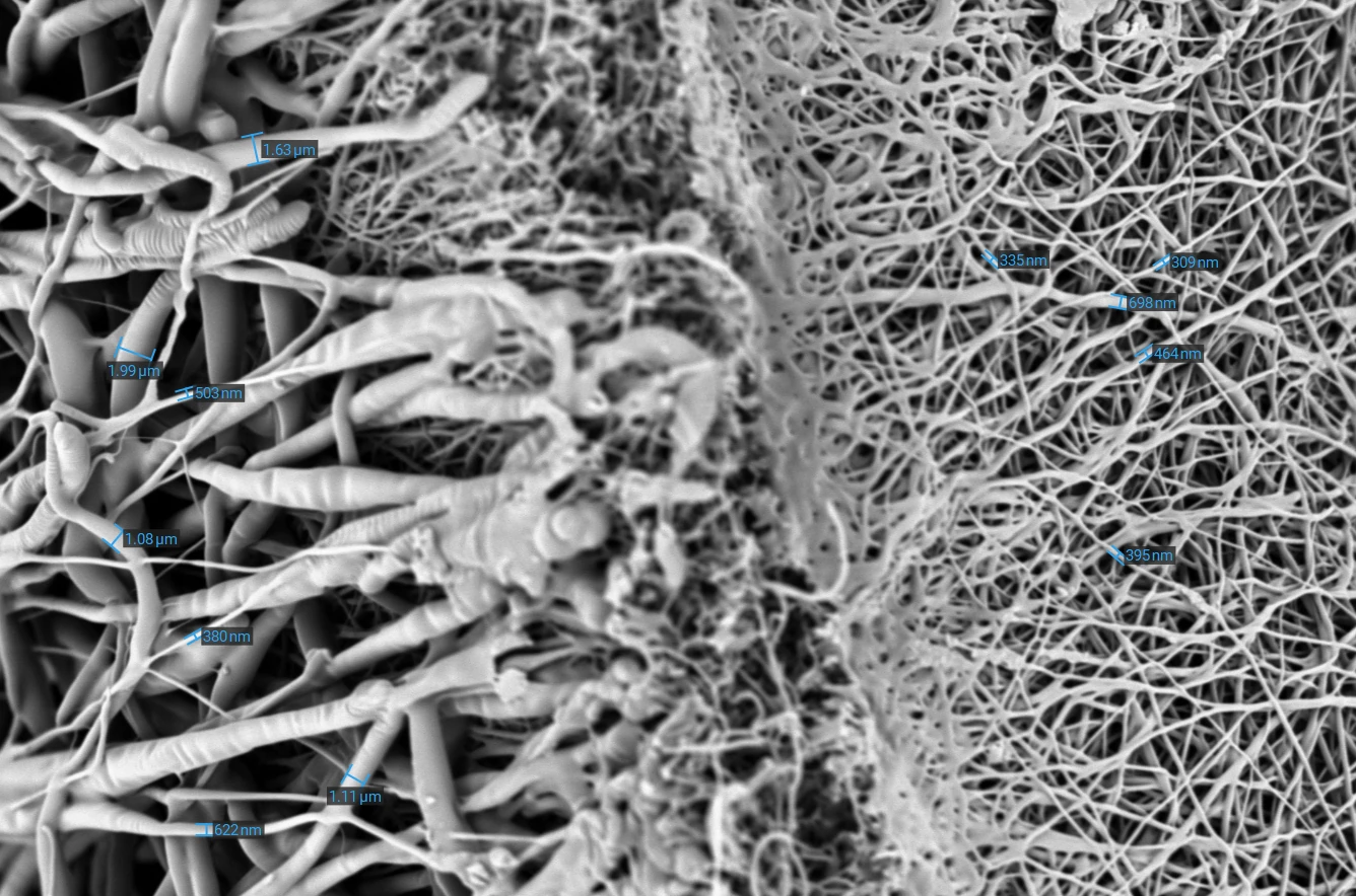
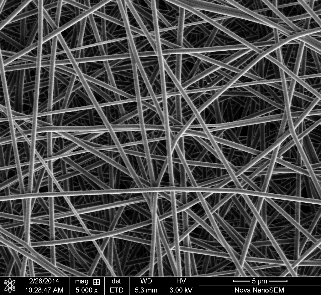
Membrane uniformity is the central focus of the TL-20M. Fine-tune the needle array and reciprocating motion, maintain stable flow in each channel, and select the collection mode for the required membrane thickness and length.

Two configurations for process scale-up

Choose the number of spinneret modules and solution throughput for your collection width, target thickness and stable operating conditions.

Compare TL-20M-200 and TL-20M-400
ParameterTL-20M-200TL-20M-400
Spinneret modules24
Maximum needle count300600
Reference solution throughputApprox. 100–200 mL/hApprox. 200–400 mL/h
Fixed-length collectionUp to 1.6 mUp to 2.75 m
Collection width200–650 mm, depending on configuration200–650 mm, depending on configuration

mL/h denotes solution throughput, not dry-fiber output. Actual output depends on solution concentration, material and process conditions.

02

Spinnerets & materials

Interchangeable modules support multi-needle, needleless and coaxial electrospinning. Choose each module for the solution system and required fiber architecture.

Coordinated control for uniform depositionEnlarge image ↗
Coordinated control for uniform deposition
Coordinated control for uniform depositionEnlarge image ↗
Coordinated control for uniform deposition

Coordinated control for uniform deposition

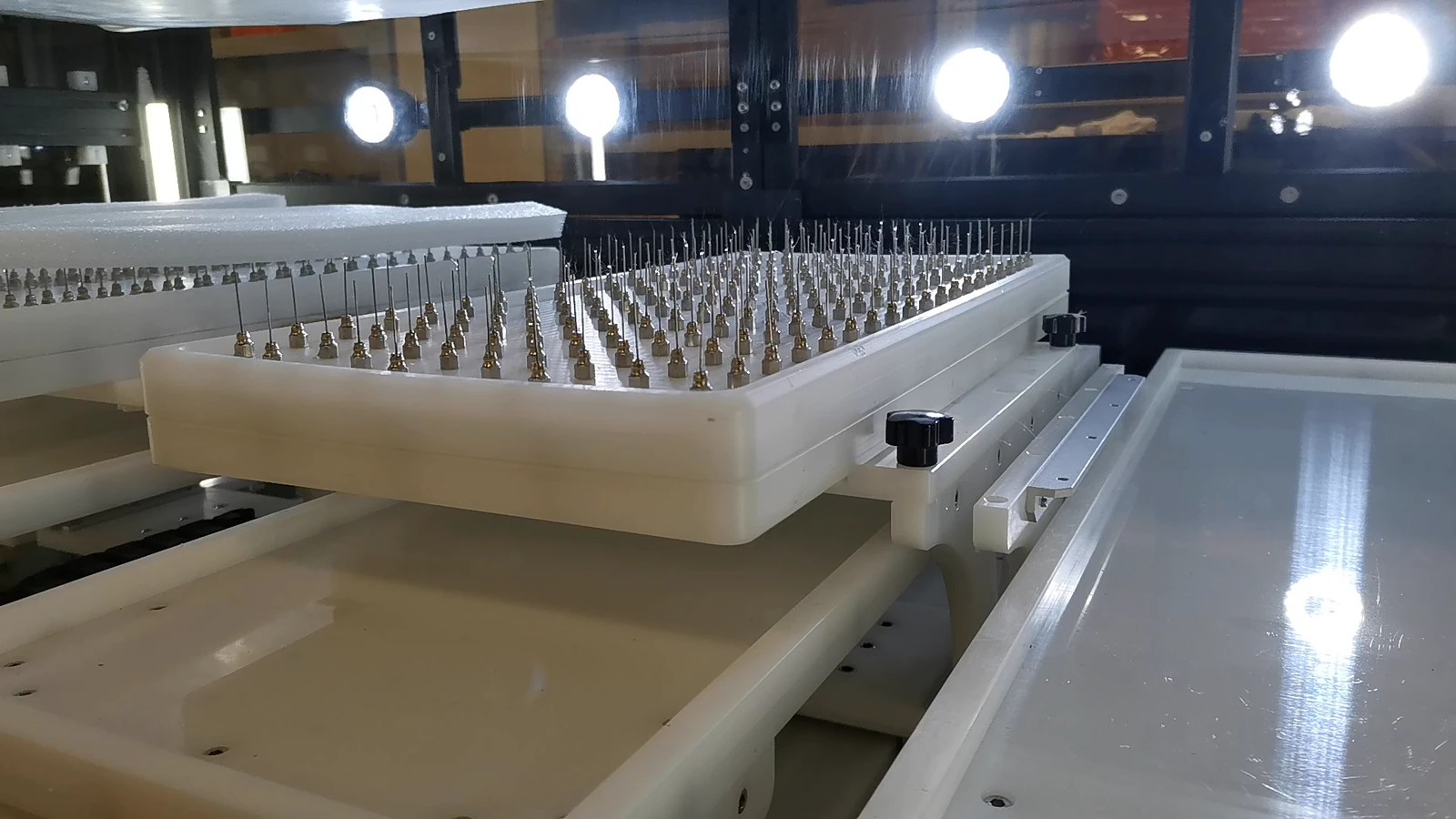
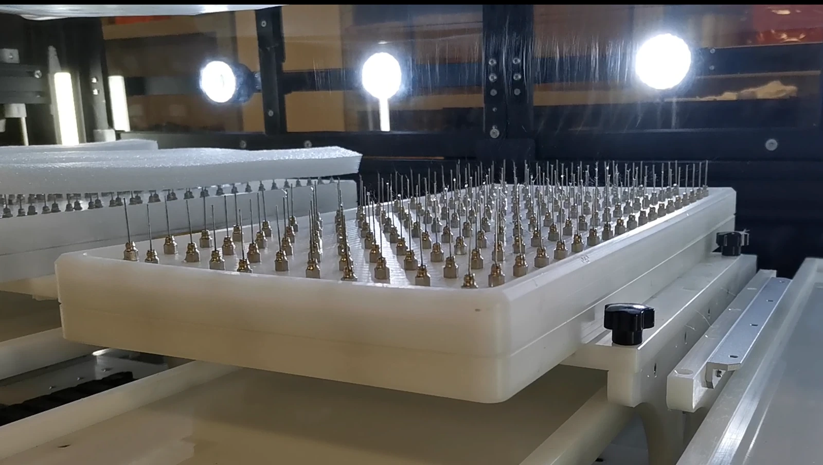
  • Adjust needle count, spacing and placement to suit the collection width and local membrane thickness profile.
  • Fine-tune array density at the edges or in selected areas to adjust local deposition.
  • Precision solution metering stabilizes the flow in each channel. A flat, conductive collection surface supports a uniform electric field.
  • Validate the process with fewer needles before expanding the array.
Reciprocating spinneret motionEnlarge image ↗
Reciprocating spinneret motion
Reciprocating spinneret motionEnlarge image ↗
Reciprocating spinneret motion

Reciprocating spinneret motion

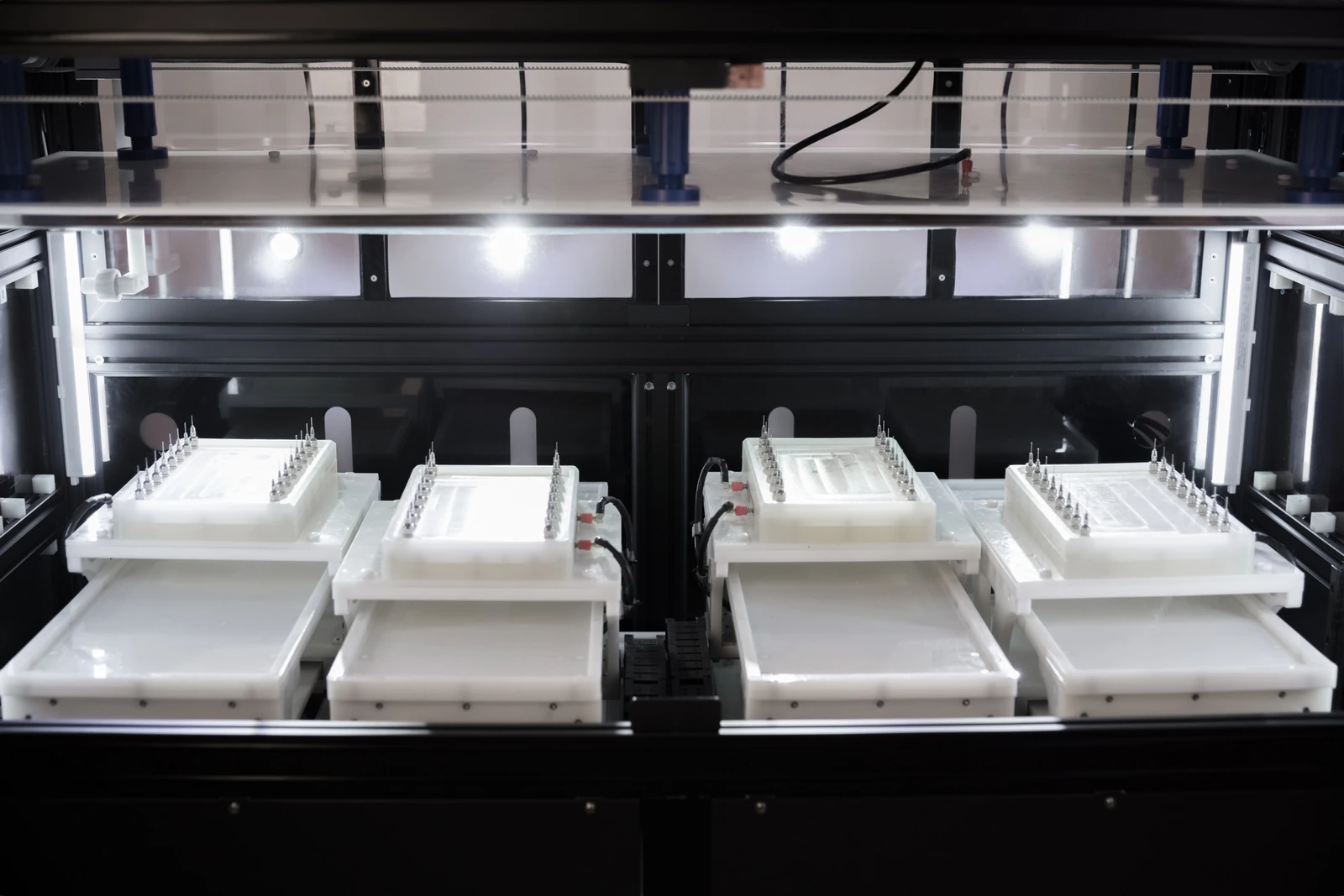
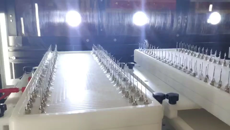
  • Spinneret modules reciprocate in opposite directions to improve coverage across the membrane width.
  • Y-axis horizontal travel: 300 mm. Speed: 1–40 mm/s.
  • Z-axis adjustment sets the spinning distance from 8 to 30 cm via the touchscreen.
  • Set motion parameters for the material and target thickness profile.
Multi-needle array systemEnlarge image ↗
Multi-needle array system

Multi-needle array system

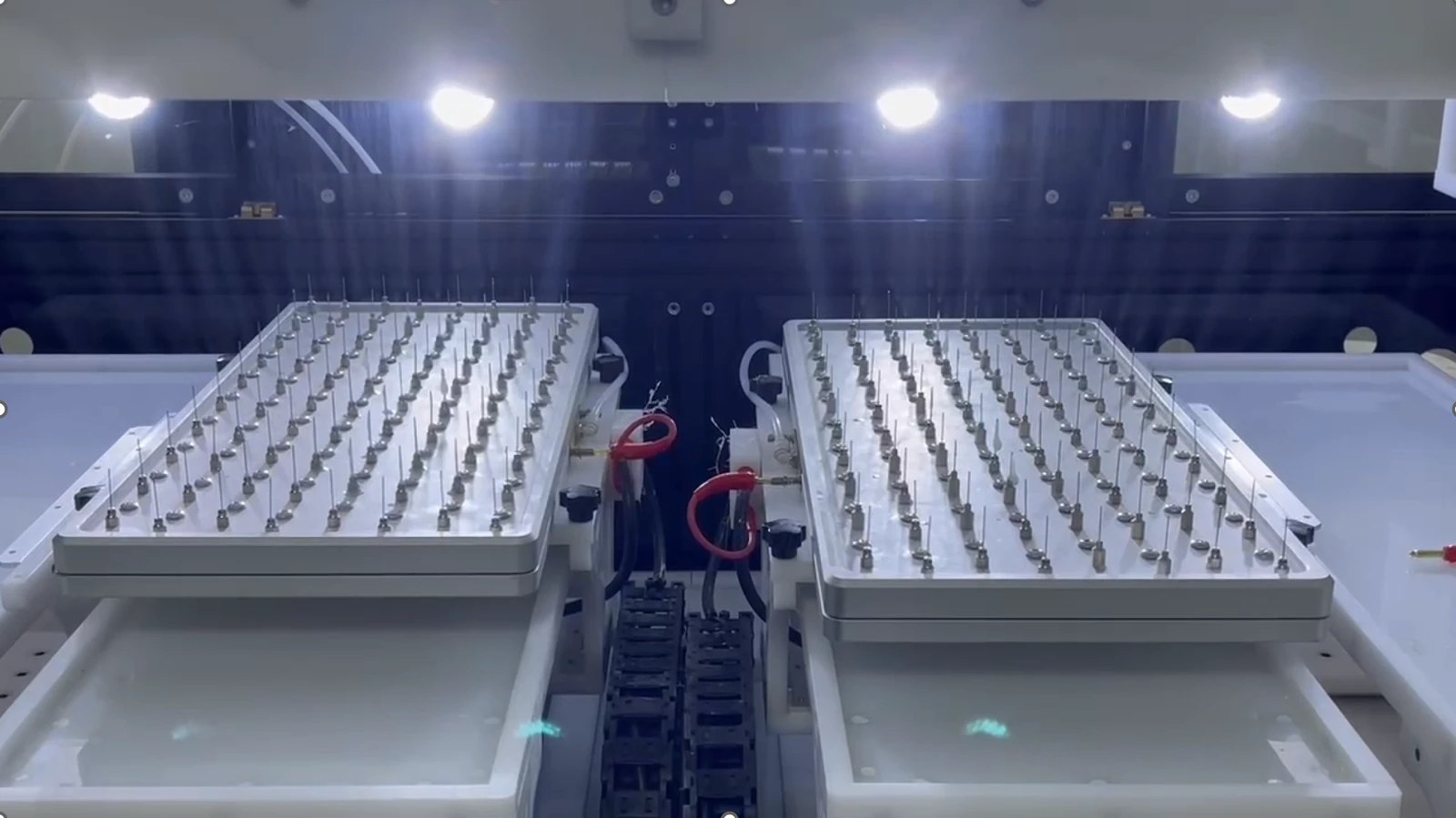
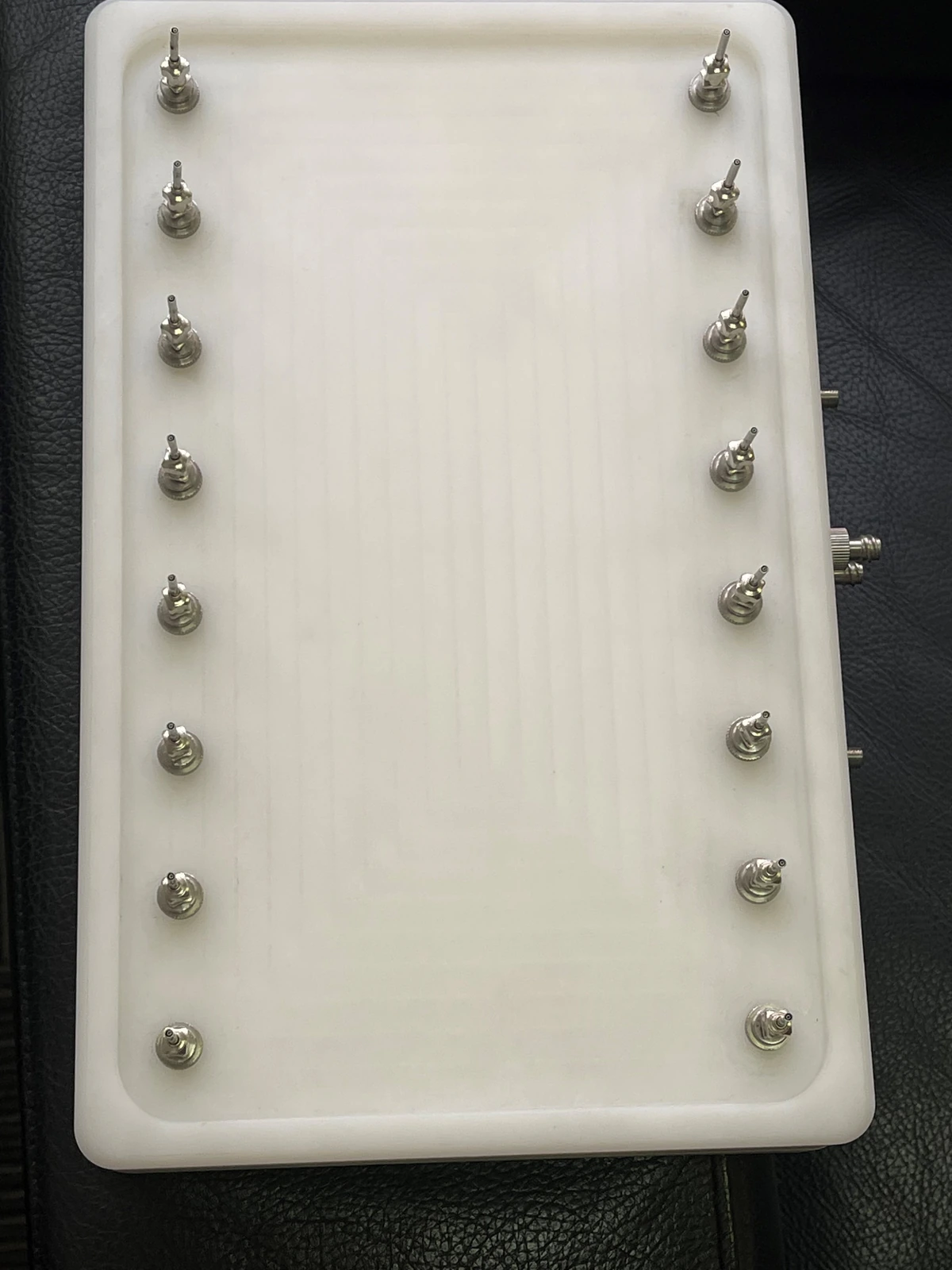
  • Configure 2–4 spinneret modules with 16–150 needles per module, depending on the configuration.
  • Process 2–4 different solutions simultaneously. Combine relative module motion and needle layout to improve deposition uniformity.
  • Precision solution delivery supports processes that require consistent results from batch to batch.
Multi-needle arrays in operationEnlarge image ↗
Multi-needle arrays in operation
Multi-needle arrays in operationEnlarge image ↗
Multi-needle arrays in operation

Multi-needle arrays in operation

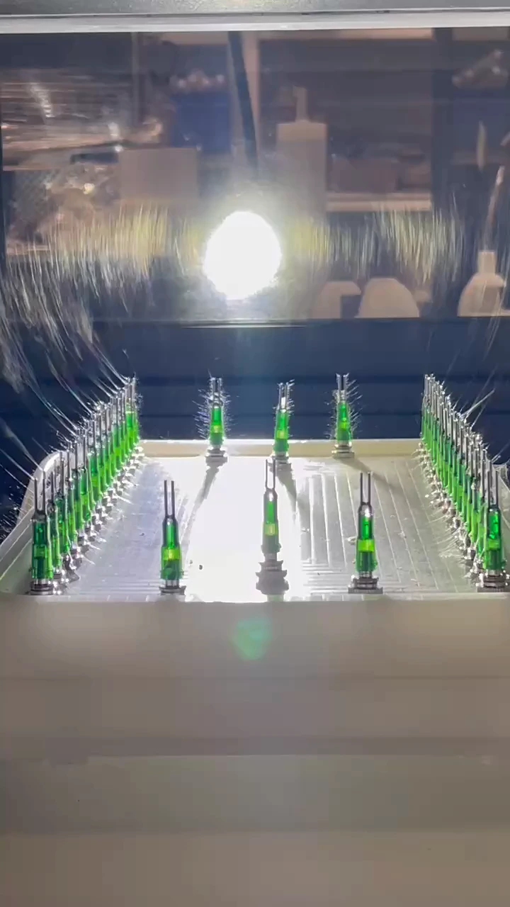
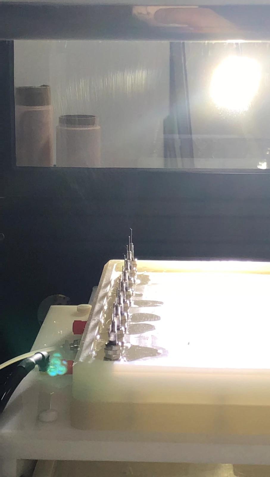
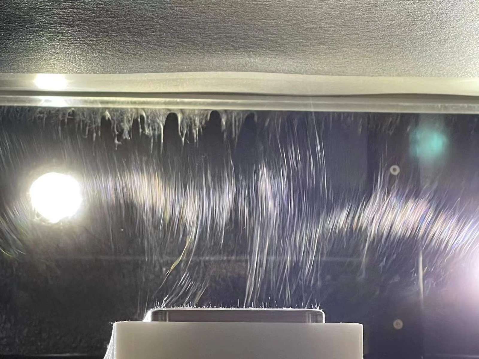
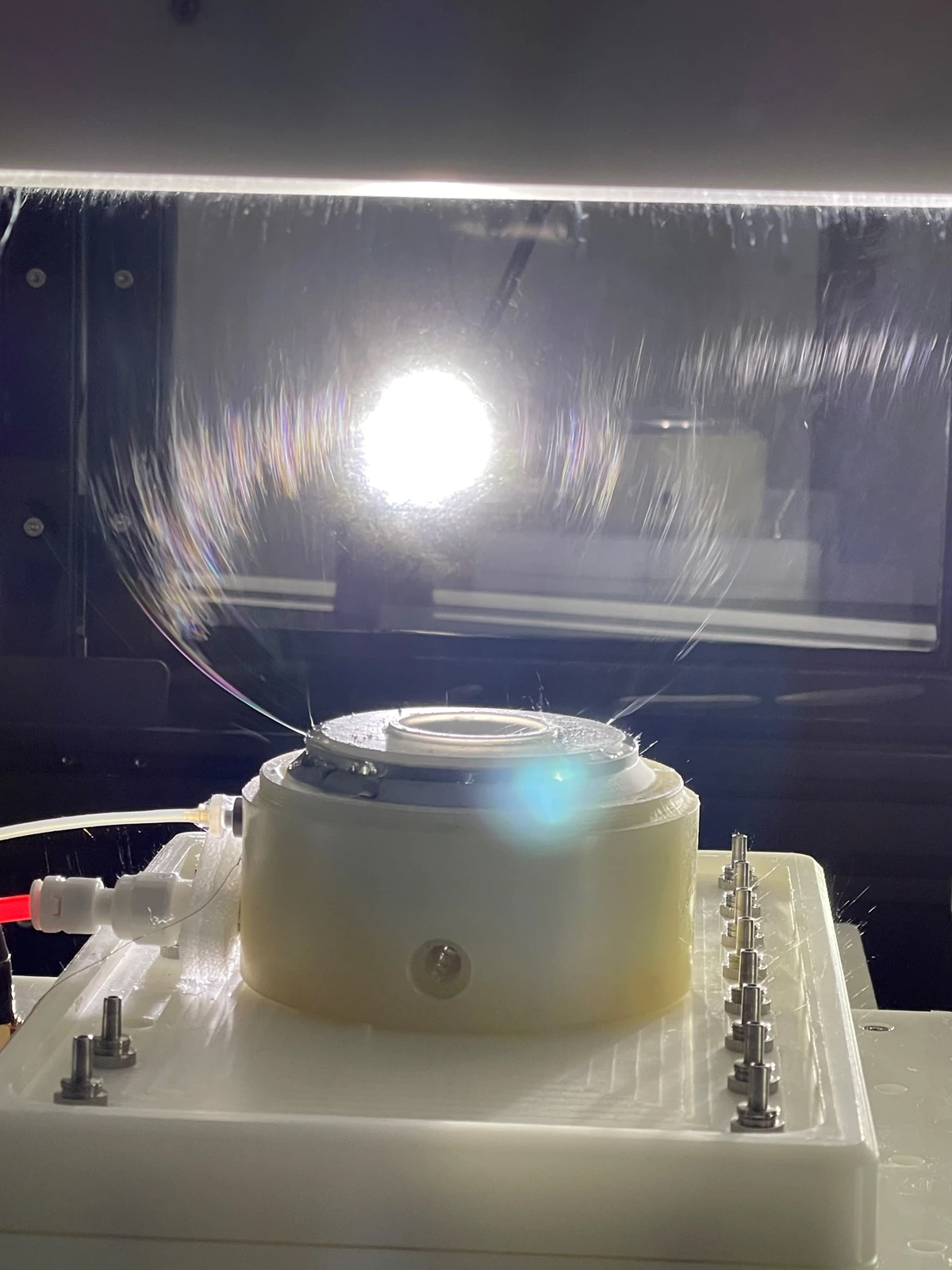
  • The photographs show an example with 100 needles × 4 modules. Select the operating needle count according to the solution formulation and process stability.
Linear needleless spinneretEnlarge image ↗
Linear needleless spinneret

Linear needleless spinneret

  • Optional module. Structural tips concentrate the local electric field.
  • The design simplifies cleaning and reduces needle consumables and individual needle maintenance.
  • Validate solvent evaporation rate and spinning stability when selecting the module.
Annular needleless spinneretEnlarge image ↗
Annular needleless spinneret

Annular needleless spinneret

  • Optional annular module for needleless electrospinning.
  • Easy cleaning supports processes requiring frequent maintenance.
  • Combine it with other spinneret modules to match the material and production requirements.
Coaxial needle arrayEnlarge image ↗
Coaxial needle array

Coaxial needle array

  • Optional module for batch production of core–shell nanofibers.
  • Independent feeds set the core and shell solution flow rates separately.
  • Replaceable inner and outer needles maintain concentric alignment. Configure the array size for the process.
Combined electrospinning and electrosprayingEnlarge image ↗
Combined electrospinning and electrospraying
Sequential electrospinning of different polymersEnlarge image ↗
Sequential electrospinning of different polymers

Multi-material and composite structures

  • Spin 2–4 materials simultaneously or sequentially to produce composite structures.
  • Examples include combined electrospinning and electrospraying, and sequential electrospinning of different polymers.

Aqueous and organic solvent systems

  • For aqueous systems, fully dissolve the polymer. For organic solvent systems, select a suitable viscosity and evaporation rate.
  • Match the solution formulation and spinneret configuration to material compatibility, process stability and operating conditions.
  • Examples include water, DMF, DMAc, DMSO, NMP, THF, HFIP and acetone.
03

Solution delivery & voltage

Independent precision solution deliveryEnlarge image ↗
Independent precision solution delivery
Independent precision solution deliveryEnlarge image ↗
Independent precision solution delivery

Independent precision solution delivery

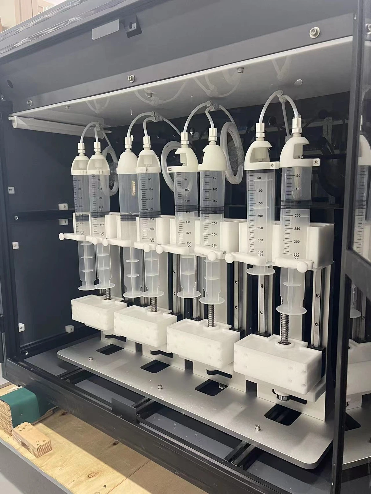
  • The separate delivery unit simplifies maintenance and expansion. Servo drives provide stable thrust and precise flow-rate control.
  • Set the feed rate independently for each channel, including core and shell feeds.
  • Capacity per channel: 200–500 mL, depending on configuration. Expand channel count to match spinneret modules and materials.
  • Select wetted components compatible with the solvent in use.
High-voltage supplies and process voltageEnlarge image ↗
High-voltage supplies and process voltage

High-voltage supplies and process voltage

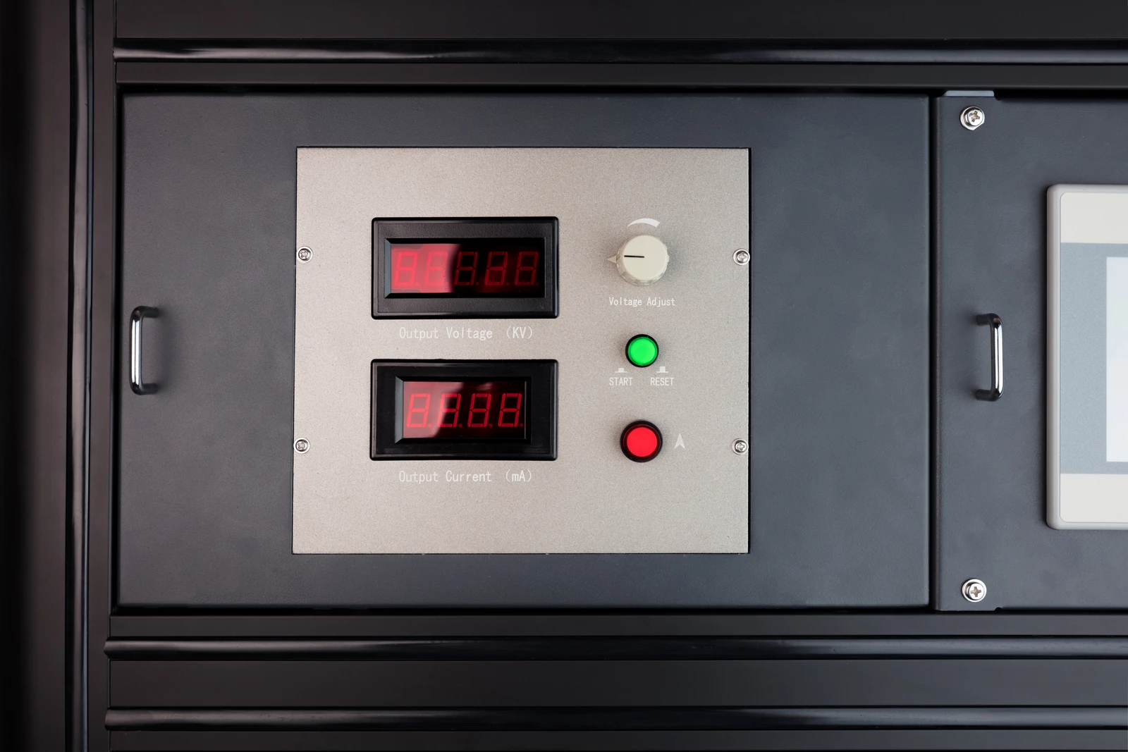
  • Process operating voltage: 40–70 kV, depending on the material, spinneret and spinning distance. This differs from the rated output range of each supply.
  • Positive output: 0 to +50 kV. Negative output: 0 to −50 kV.
  • Current range: 0–3 mA. Automatic shutdown above 3000 μA.
  • Voltage falls from 50 kV to 0 in less than 0.5 s after switch-off. Power-supply accuracy: ±(2.0% rdg + 1 digit).
  • The optimized needle-array and electric-field layout supports operation at lower process voltages to help reduce unintended sparking and discharge.
04

Collection modes

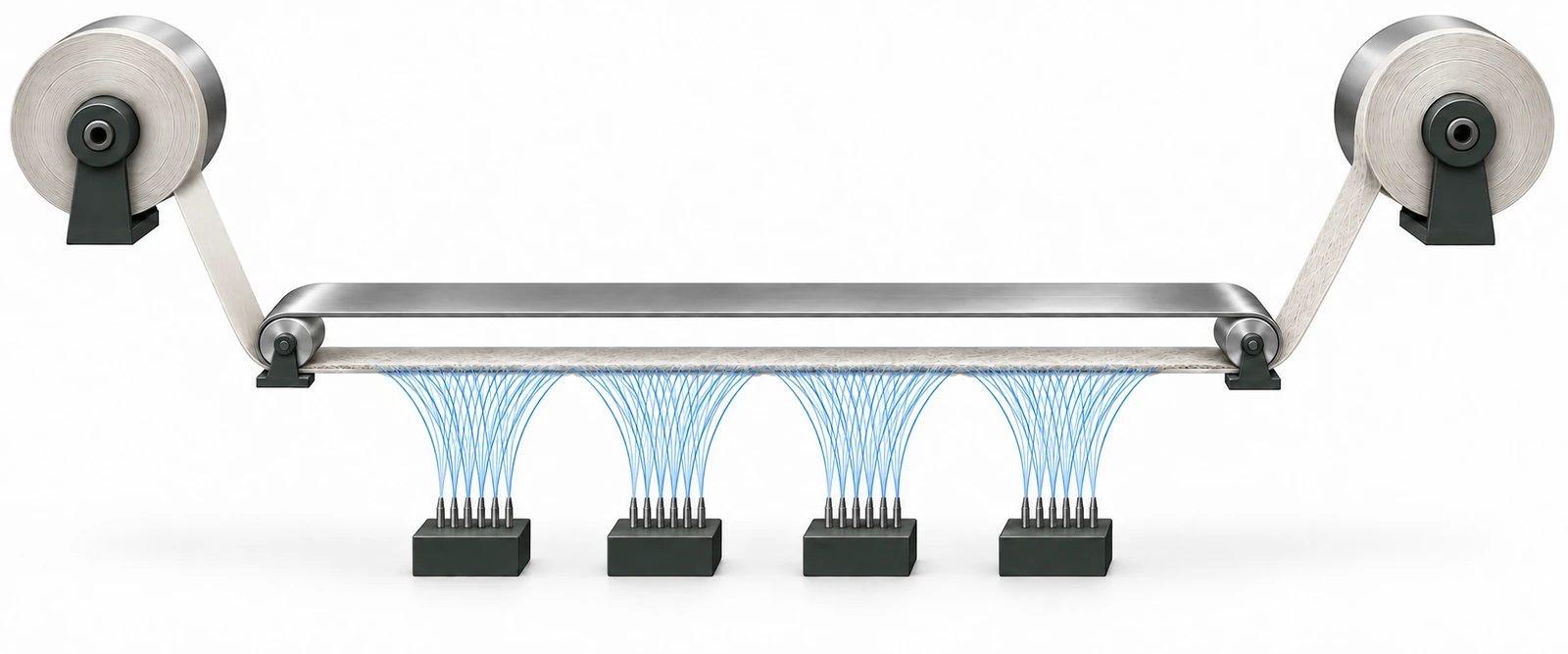
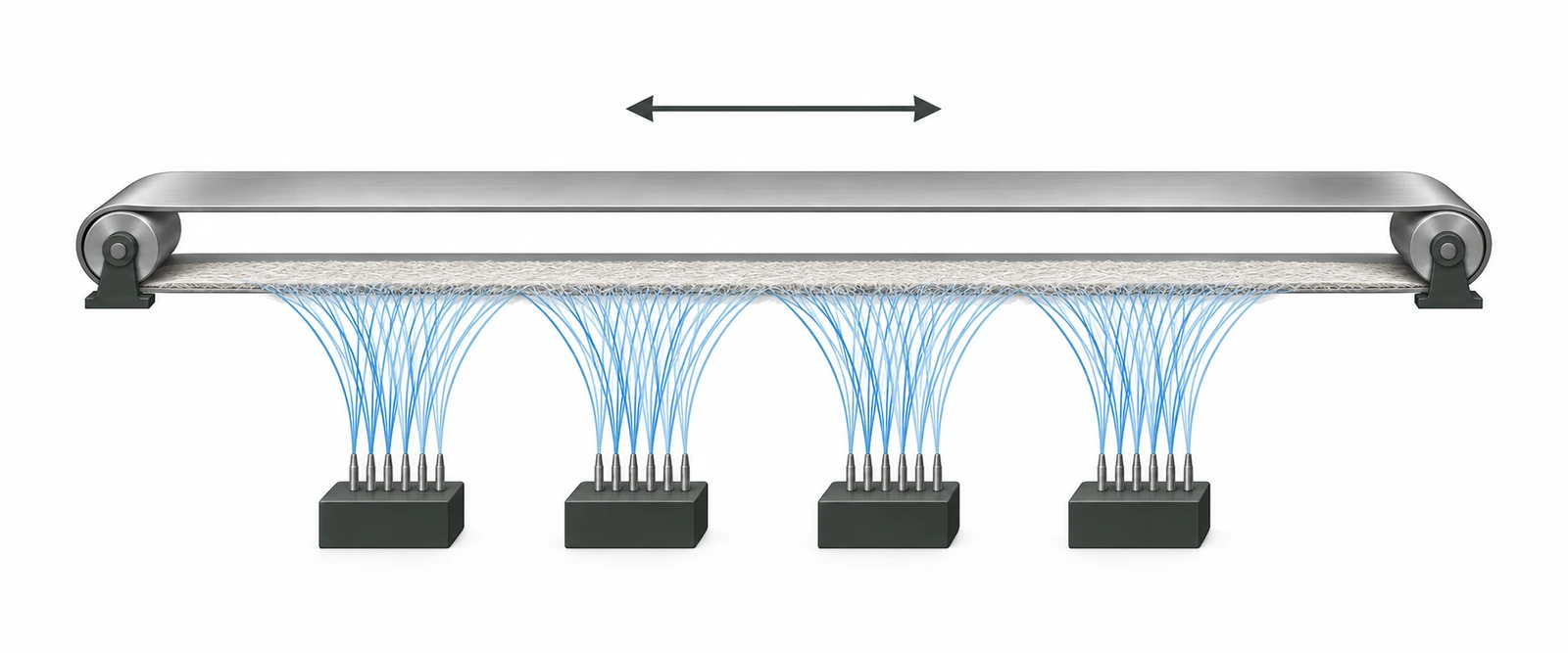
Both modes use upward electrospinning, with spinnerets below and the collector above. Select continuous winding for rolls, or repeated deposition on a closed loop for thick mats.

Continuous roll collectionEnlarge image ↗
Continuous roll collection
Fixed-length thick-mat collectionEnlarge image ↗
Fixed-length thick-mat collection

Collection principle schematics, not equipment engineering drawings.

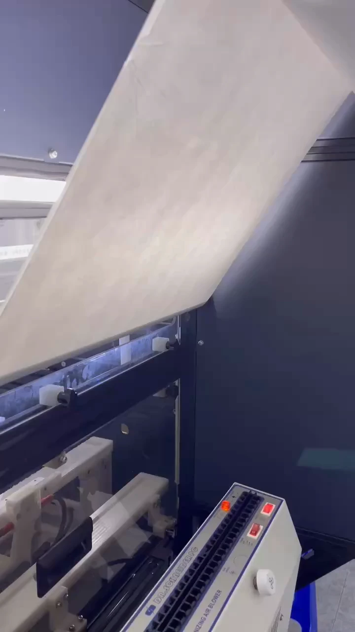
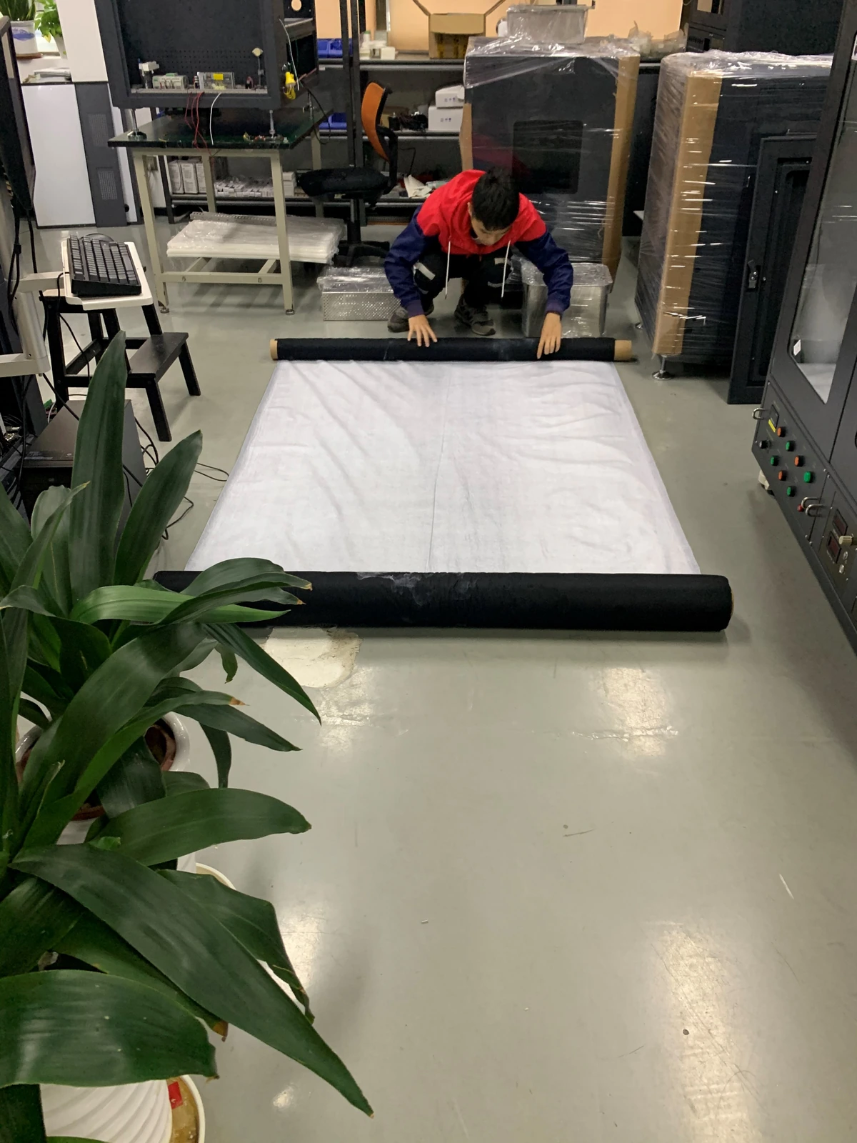
Continuous roll-to-roll collectionEnlarge image ↗
Continuous roll-to-roll collection

Continuous roll-to-roll collection

  • A closed-loop stainless-steel belt runs around two rollers and supports the membrane in the spinning zone. The membrane winds immediately after leaving this zone.
  • Collection width: 200–650 mm, depending on configuration.
  • Continuous winding length: approximately 200 m, depending on the collection configuration.
  • Maximum roll diameter: 500 mm. Winding speed: 0–20 mm/min.
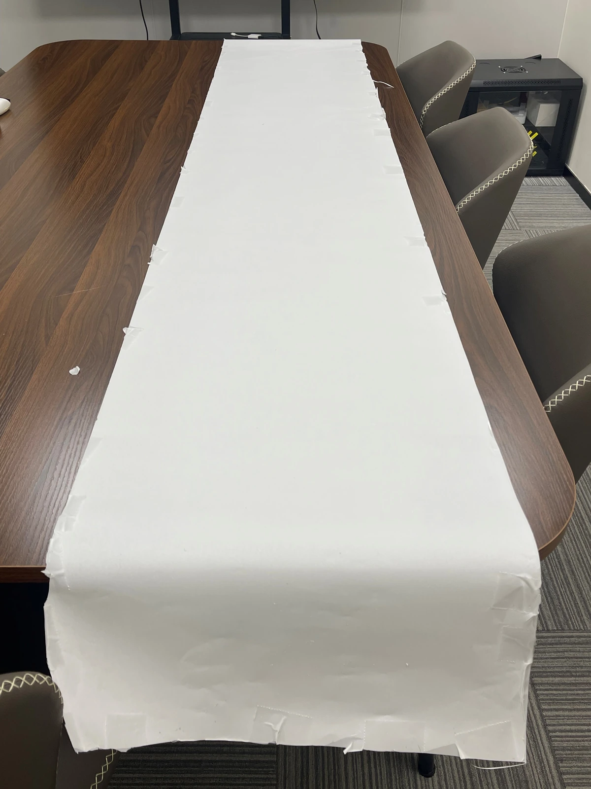
Fixed-length thick fibrous matsEnlarge image ↗
Fixed-length thick fibrous mats

Fixed-length thick fibrous mats

  • Repeated deposition on the closed loop builds membrane thickness over a fixed collection length.
  • TL-20M-200: up to 1.6 m. TL-20M-400: up to 2.75 m.
  • Collect on metal substrates such as aluminum foil. Reference thickness: ≥50 μm. Actual thickness depends on the material and deposition time.
05

Control & maintenance

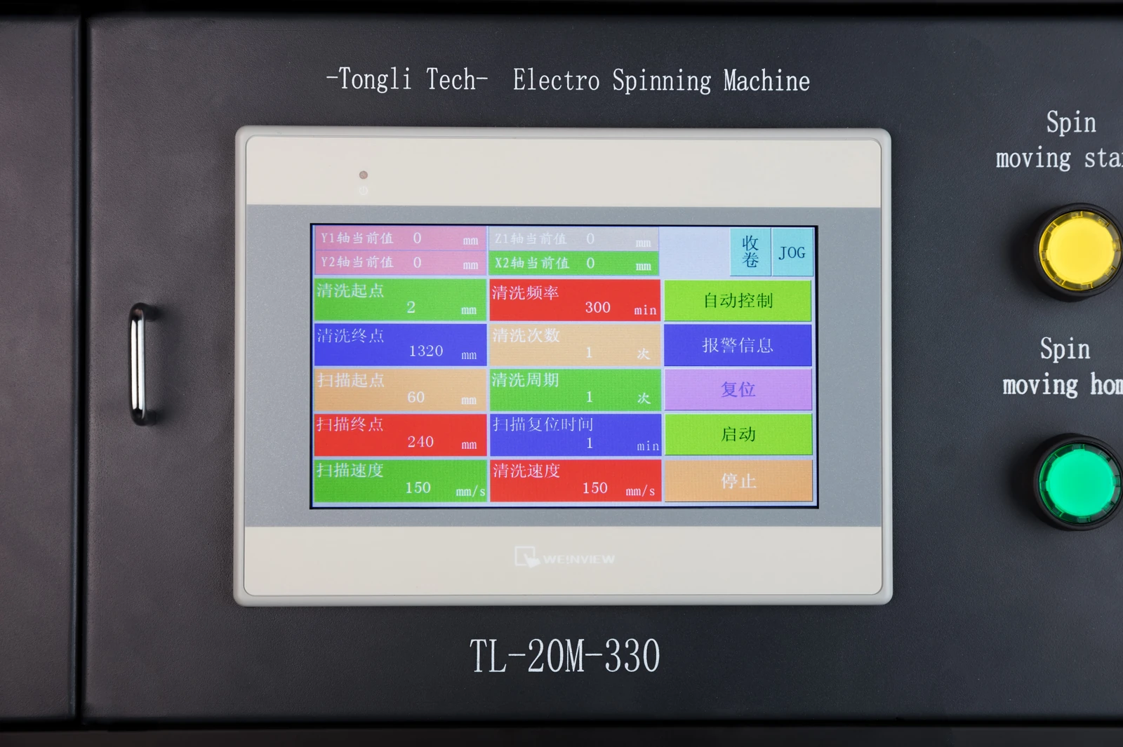
Touchscreen process controlEnlarge image ↗
Touchscreen process control

Touchscreen process control

  • Set motion, cleaning and other process parameters through the central touchscreen.
  • Choose separate high-voltage control or control through the touchscreen.
  • Retrieve approximately one month of process parameter history to support repeat production.
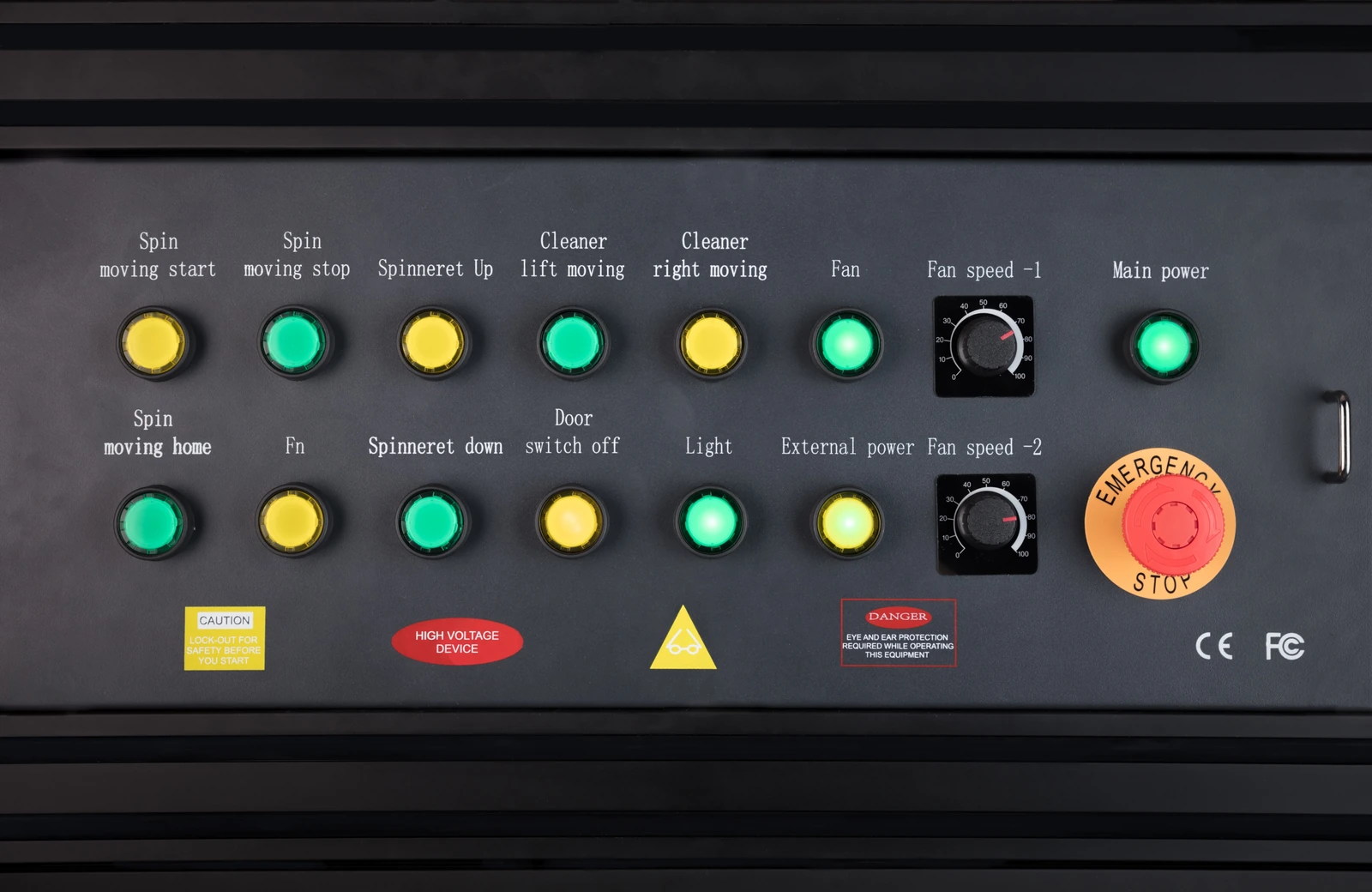
Direct access to operating controlsEnlarge image ↗
Direct access to operating controls

Direct access to operating controls

  • Physical buttons control spinning and collection start/stop, spinneret positioning, needle cleaning, exhaust and lighting.
  • A physical emergency-stop button allows prompt intervention.

Automatic needle cleaning during production

  • Automatic cleaning reduces manual intervention during the production cycle.
  • Set the cleaning frequency to match the solution and its tendency to clog.
  • Disposable cleaning media allow straightforward replacement and routine maintenance.
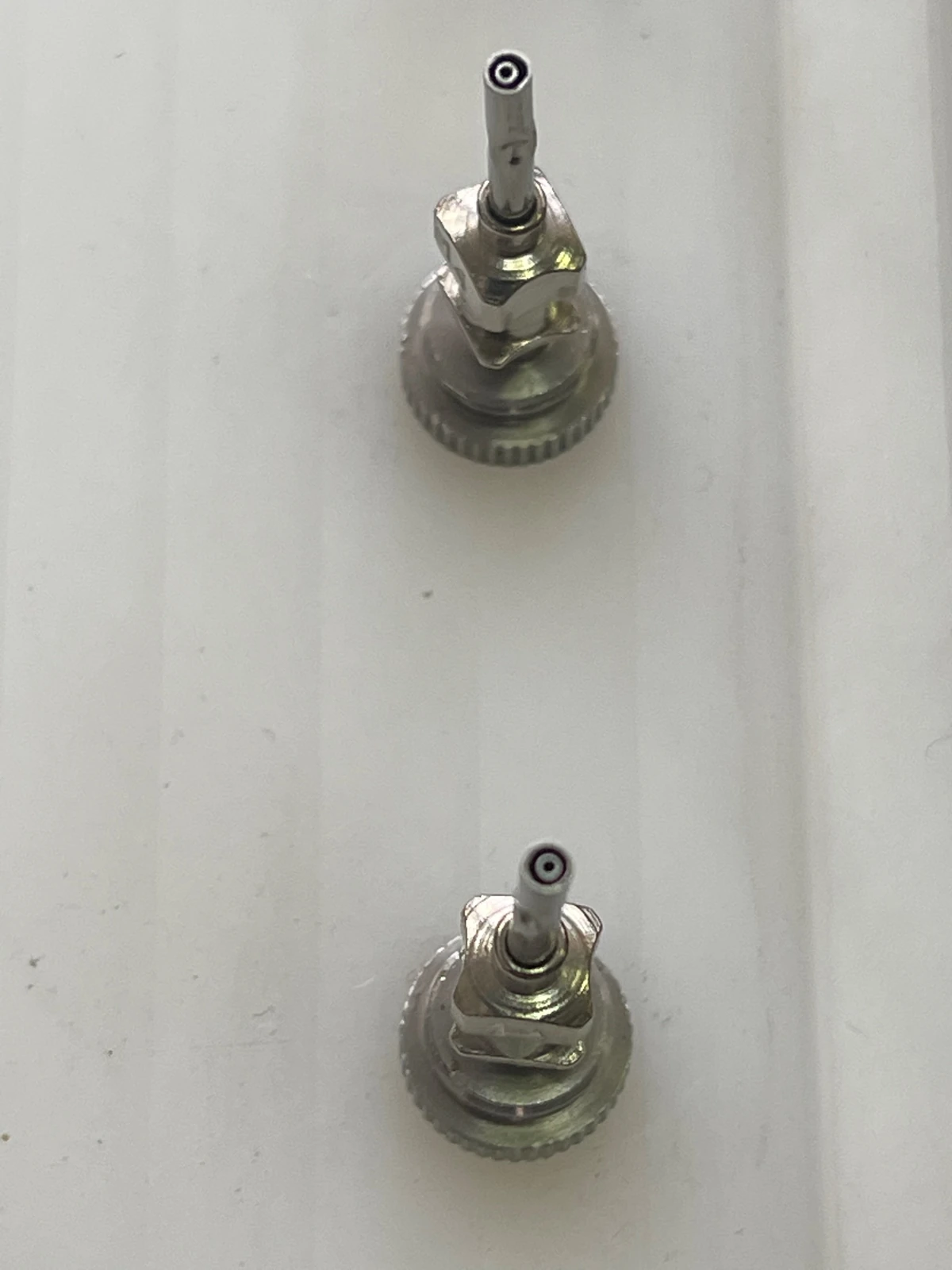
Needle maintenance and replacementEnlarge image ↗
Needle maintenance and replacement

Needle maintenance and replacement

  • Seal needles with dedicated caps after production.
  • Simple twist or pull actions allow quick removal and replacement when needed.
  • Full-array replacement takes approximately 10–20 minutes, depending on needle count and configuration.
06

Samples & installation

External dehumidification

  • An external dehumidifier can reduce humidity to approximately 20%–30% RH. Adjust humidity for the material and process.
  • The external unit is easy to install and maintain in conventional laboratories or production facilities.
  • Achievable humidity depends on ambient conditions, enclosure sealing and operating conditions.

Protection and operating interlocks

  • High-voltage, overvoltage and overcurrent protection trigger an alarm when parameter limits are exceeded.
  • A door-open power interlock and emergency-stop button support prompt interruption of operation.
  • Static elimination, multi-point grounding and proper operating procedures form part of the installation and operating arrangements.
  • Match needle layout and operating voltage to the process, together with the appropriate protective devices.

Installation requirements

  • Install the system in a laboratory or production facility with utilities suited to the solvent and process.
  • Configure ventilation and exhaust for the solvent system and production conditions.
  • Provide multi-point grounding and static elimination, and adjust humidity to meet material requirements.

Plan your membrane process

  1. 01

    Define the product

    Specify membrane width, thickness and fiber structure. Choose continuous or fixed-length collection.

  2. 02

    Select spinneret modules

    Choose multi-needle, needleless or coaxial modules for the solution system and required fiber architecture.

  3. 03

    Scale a stable process

    Validate with fewer needles, then increase needle count and solution throughput while checking membrane uniformity and batch consistency.

Customer equipment reference

TL-20M at a research institution

An equipment listing published on the customer’s own website.

Explore institutional and research records →

Tell us what you want to make.

Share your material, target structure and sample size. We can discuss a suitable platform and configuration.

Discuss your application