Electrowriting & EHD printing

TL-EHD

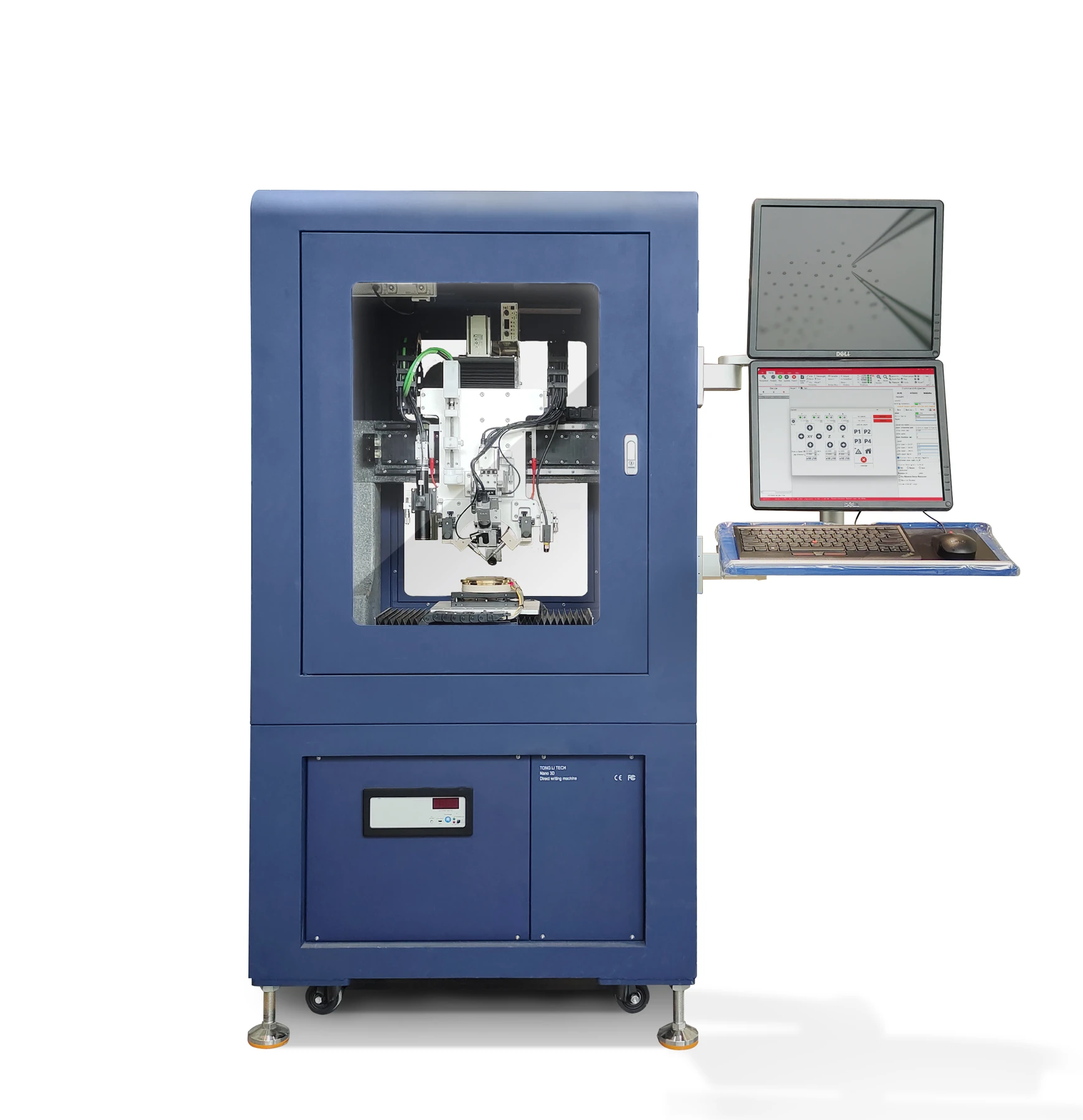
Electrohydrodynamic Micro/Nano Printer

Print microscale dots, lines and multilayer patterns with electric-field-driven droplet deposition. Programmable voltage waveforms, coordinated motion and four camera views support process development and inspection.

1–45 μm
Dot and line feature size
0–2000 V
High-voltage output
4
Independent camera views

Actual feature size depends on the material and process.

01

Platform & process

Integrated printing and process controlEnlarge image ↗
Integrated printing and process control

Integrated printing and process control

Voltage waveforms control droplet ejection and deposition. Four camera views work alongside closed-loop motion control, while pattern import, drawing and parametric editing turn the intended geometry into a print path.

Near-field droplet printingEnlarge image ↗
Near-field droplet printing

Near-field droplet printing

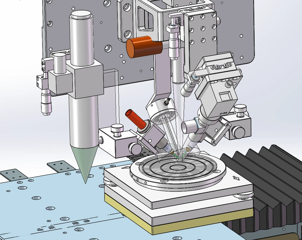
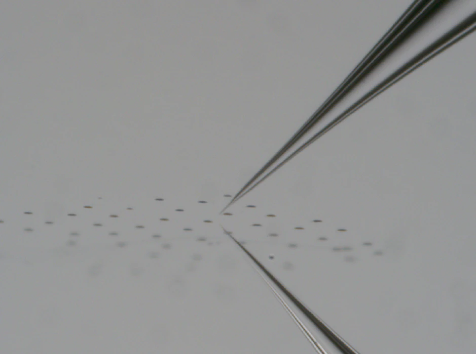
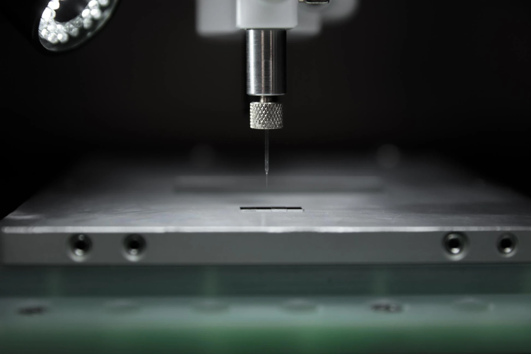
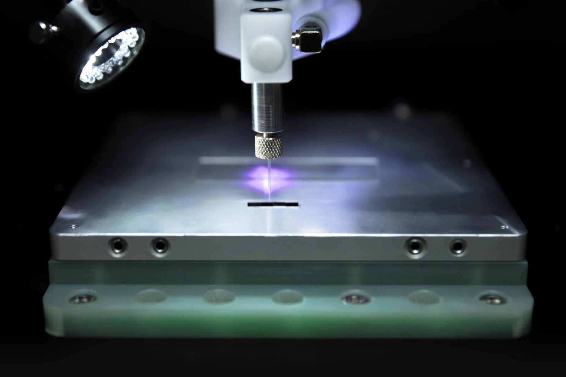
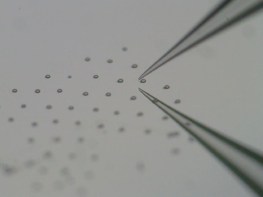
The nozzle tip operates tens to hundreds of micrometers above the substrate. The electric field ejects discrete droplets onto defined positions. Synchronized motion and jetting overlap adjacent deposits to form lines and complex patterns.

Three processes, different structures

ElectrospinningEnlarge image ↗
Electrospinning

Electrospinning

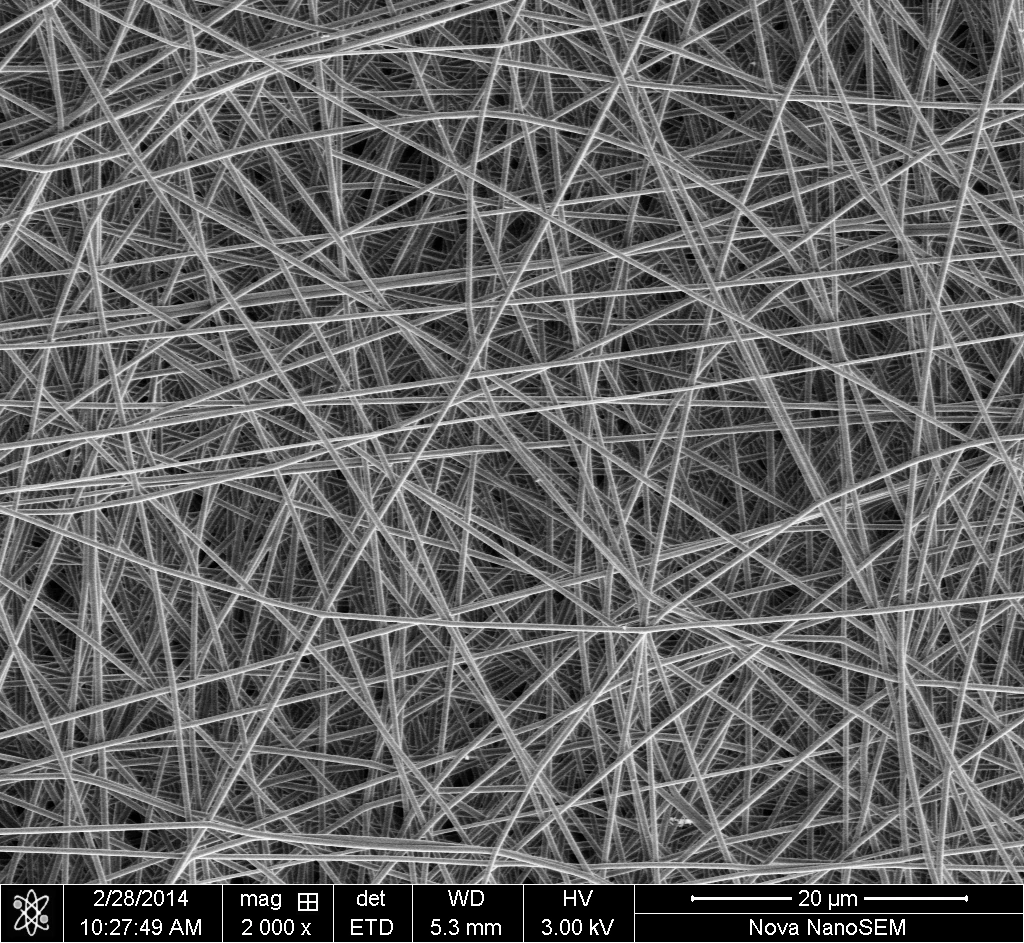
Multiple fibers form a membrane. Typical fiber diameters are 100–1000 nm.

Electrostatic direct writingEnlarge image ↗
Electrostatic direct writing

Electrostatic direct writing

Individual solution or melt fibers are placed directly, layer by layer, to create ordered structures.

EHD jet printingEnlarge image ↗
EHD jet printing

EHD jet printing

Droplets form dots. Overlapping deposits form lines and fine patterns. This is the focus of TL-EHD.

Machine architectureEnlarge image ↗
Machine architecture

Machine architecture

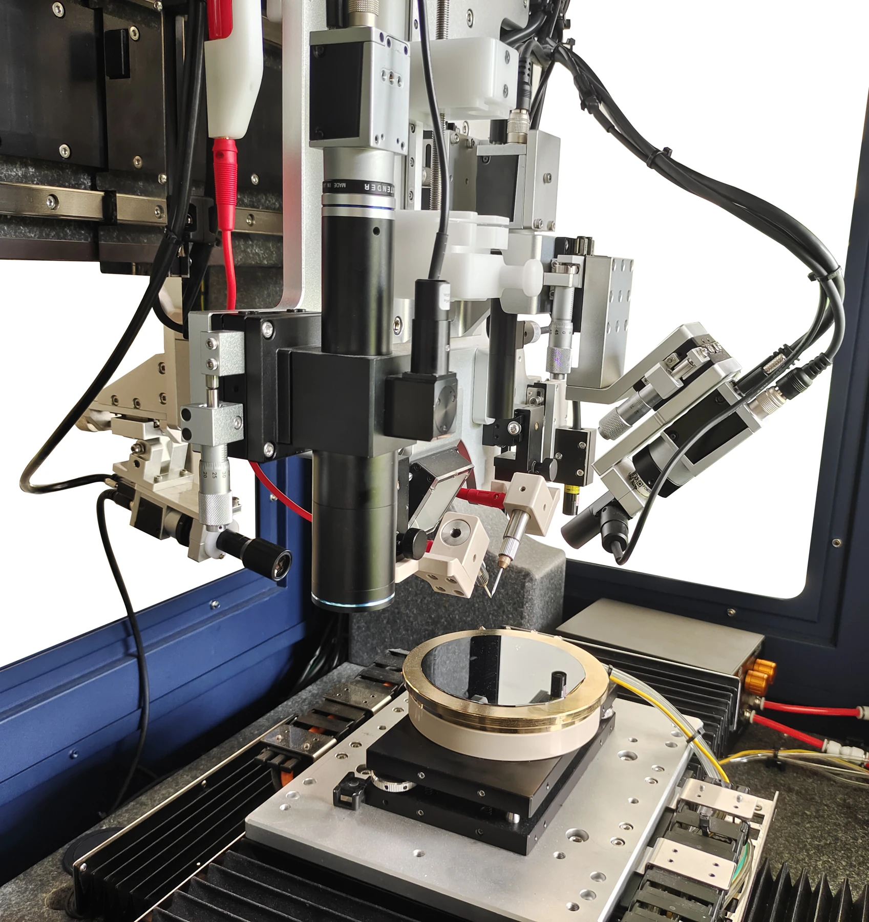
Access from all four sides supports sample loading, maintenance and upgrades. A marble base supports the precision motion system. Two large-format displays show motion, camera views, waveforms and signal feedback. System dimensions: 1613 × 908 × 724 mm. Approximate weight: 500 kg.

02

Motion & electric field

X–Y–Z–K closed-loop motion

Linear motors drive X, Y and K. A rotary servo motor drives Z. Closed-loop control coordinates positioning and path execution.

AxisTravelMaximum speedPositioning specification
X>180 mm200 mm/sRepeatability: ±1.5 μm
Y>180 mm200 mm/sRepeatability: ±1.5 μm
Z>80 mm20 mm/sPositioning accuracy: 100 nm

100 nm and ±1.5 μm are stage positioning specifications. Actual print placement accuracy depends on the material and process.

Adjustable high-voltage outputEnlarge image ↗
Adjustable high-voltage output

Adjustable high-voltage output

Digitally controlled, programmable output from 0 to 2000 V. The output current is continuously adjustable from 0 to 10 mA.

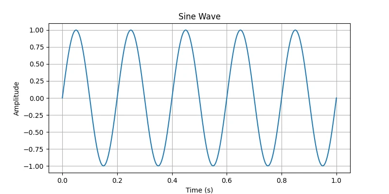
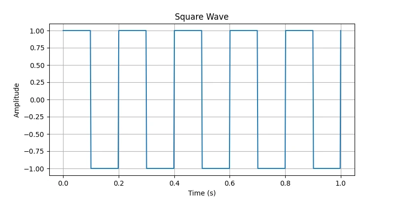
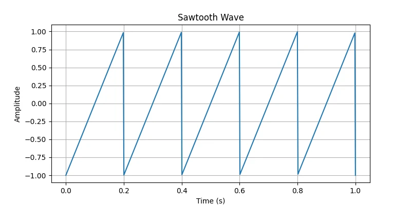
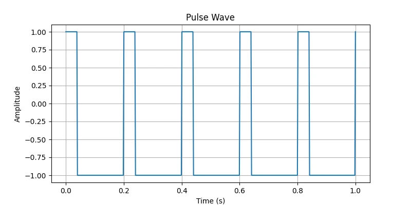
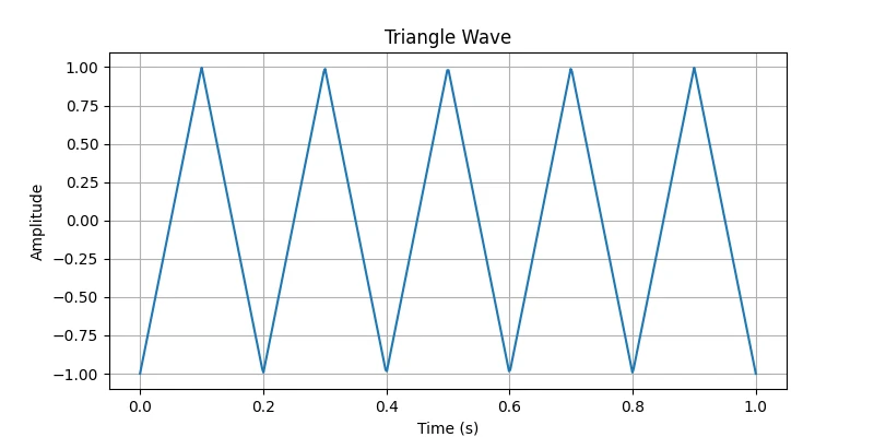
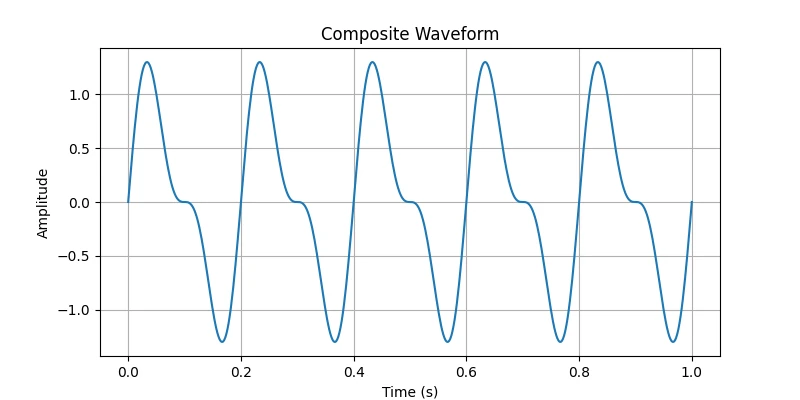
Programmable voltage waveforms

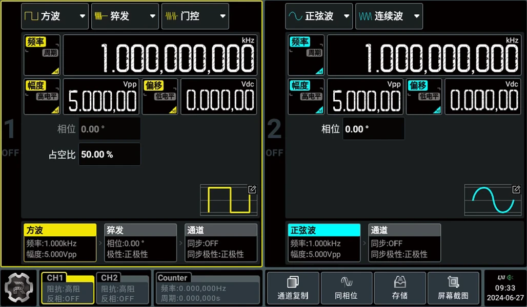
Set frequency, duty cycle, amplitude and DC offset from the PC. Standard, composite and custom waveforms are available, with Chinese and English software interfaces.

Programmable voltage waveformsEnlarge image ↗
Programmable voltage waveforms
Programmable voltage waveformsEnlarge image ↗
Programmable voltage waveforms
Programmable voltage waveformsEnlarge image ↗
Programmable voltage waveforms
Programmable voltage waveformsEnlarge image ↗
Programmable voltage waveforms
Programmable voltage waveformsEnlarge image ↗
Programmable voltage waveforms
Programmable voltage waveformsEnlarge image ↗
Programmable voltage waveforms
Digital oscilloscope monitoringEnlarge image ↗
Digital oscilloscope monitoring

Digital oscilloscope monitoring

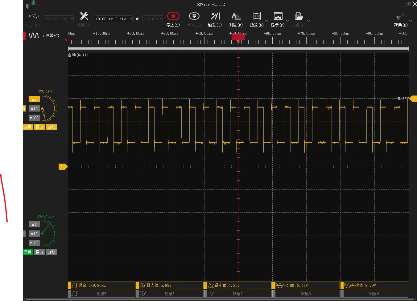
A dual-channel USB oscilloscope monitors voltage and pulses during process adjustment. Analog bandwidth: 50 MHz. Sampling rate: up to 200 MSa/s. Sensitivity: 10 mV/div–2 V/div. Input range: −100 V to +100 V (DC + AC).

03

Materials & delivery

Materials and ink selection

Material classInk type / examplesPotential applications
Conductive inksSilver nanoparticle and silver-ion inks, PEDOT:PSS dispersionsMicroelectrodes and conductive traces
Polymer solutionsSolutions of insulating or functional polymersInsulating patterns and functional microstructures
Particle dispersionsStable dispersions, such as semiconductor nanoparticlesFunctional layers and microscale patterns
Photocurable inksJettable UV-curable resins or prepolymersLocalized curing and microstructure fabrication

Validate each formulation with the nozzle, waveform, feed settings and substrate. Assess viscosity, conductivity and surface tension, dispersion stability, settling and clogging. Match substrate wetting, drying and curing conditions. Photocurable inks require a compatible light source.

Microscale nozzles and holdersEnlarge image ↗
Microscale nozzles and holders

Microscale nozzles and holders

Nozzle sizes range from 1 to 100 μm. Select the bore for the ink viscosity and target pattern. Smaller bores are generally used with lower-viscosity inks. Dedicated holders connect the nozzles to the fluid delivery system.

Dual printheads with manual switchingEnlarge image ↗
Dual printheads with manual switching

Dual printheads with manual switching

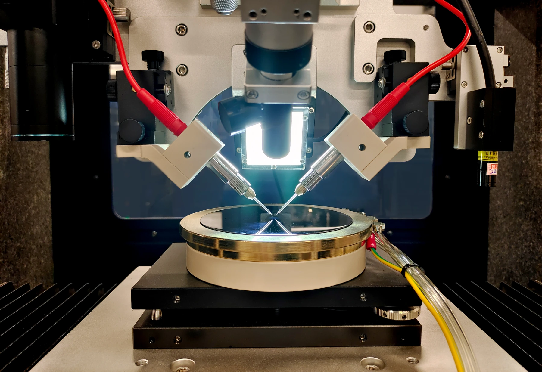
Two microscale nozzles support simultaneous or alternating operation. Each nozzle has independent X–Y–Z adjustment. Multiple observation views assist alignment and in-process inspection.

Precision syringe-based ink deliveryEnlarge image ↗
Precision syringe-based ink delivery
Precision syringe-based ink deliveryEnlarge image ↗
Precision syringe-based ink delivery

Precision syringe-based ink delivery

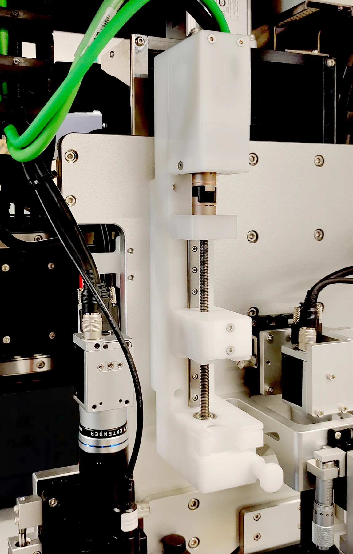
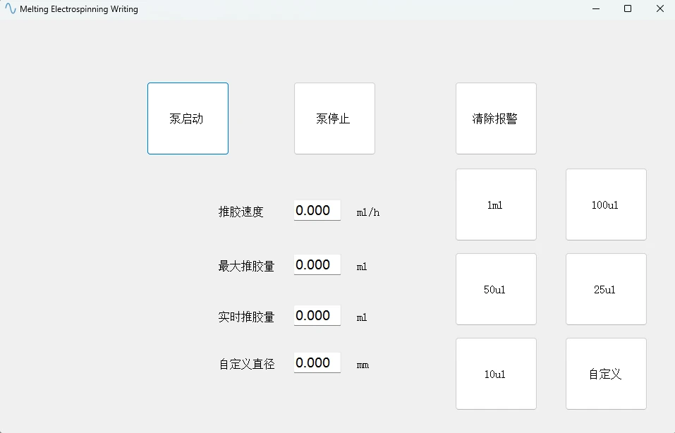
Flow rate: 0.01 μL/h to 99.9 mL/h. Fluid viscosity: 300–5000 cP. Compatible syringe volumes: 1, 10 and 20 mL. Luer-tip stainless-steel needles use bores selected to suit the ink.

Vacuum chuck and substrate mountingEnlarge image ↗
Vacuum chuck and substrate mounting
Vacuum chuck and substrate mountingEnlarge image ↗
Vacuum chuck and substrate mounting

Vacuum chuck and substrate mounting

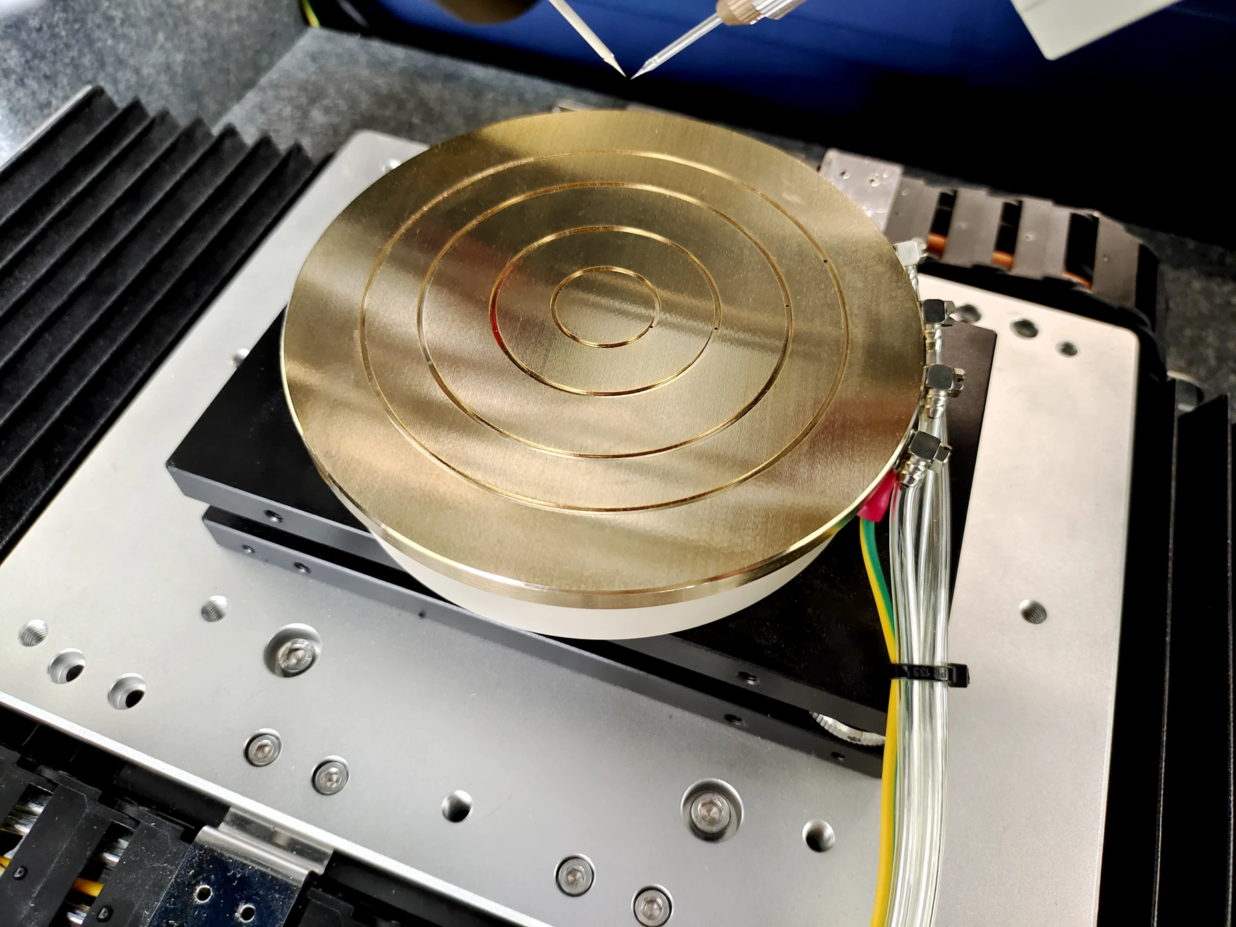
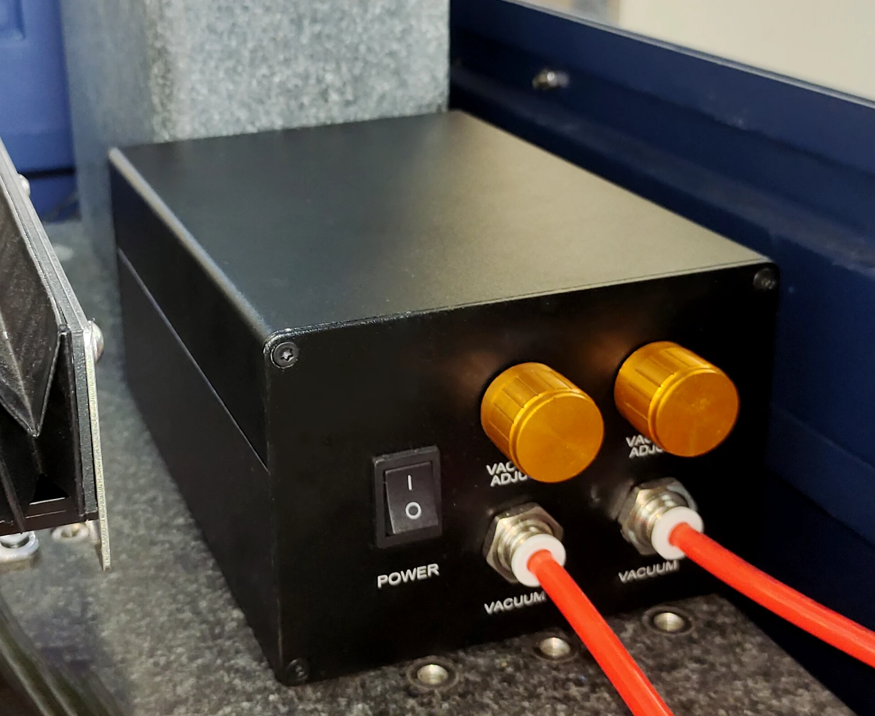
A multi-ring gold-plated vacuum chuck supports 1, 2, 3 and 4 inch silicon wafers. It allows level adjustment and provides electrical insulation for high-voltage operation. A quiet dual-channel vacuum pump offers adjustable suction for sample holding and exchange.

365 nm UV curingEnlarge image ↗
365 nm UV curing

365 nm UV curing

Control curing independently or in synchronization with printing. Programmable curing follows the path sequentially or synchronously. The source moves with the Z axis, with fine adjustment relative to the nozzle. Four lateral operating positions can be stored and recalled.

04

Vision & software

Four-channel microscopic imaging

Alignment cameraEnlarge image ↗
Alignment camera

Alignment camera

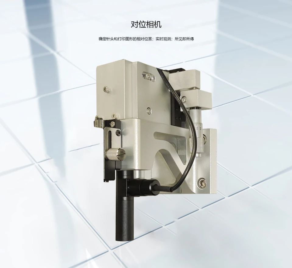
Locates the nozzle relative to the pattern.

Gap measurementEnlarge image ↗
Gap measurement

Gap measurement

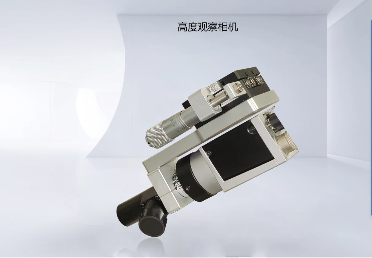
Observes and measures the nozzle-to-substrate gap.

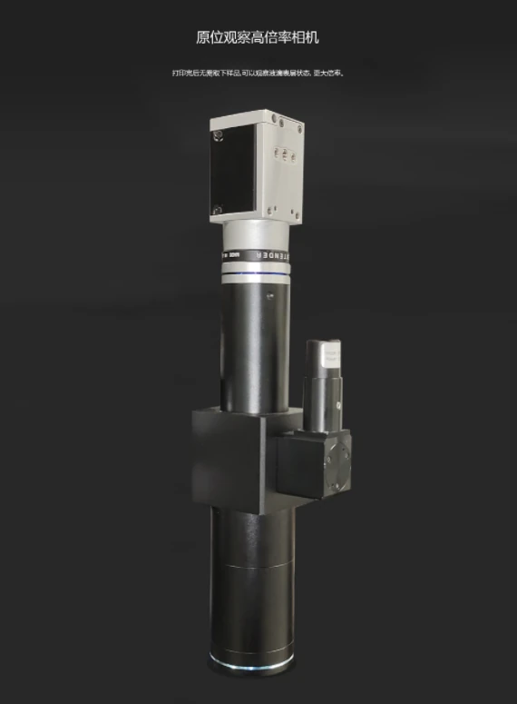
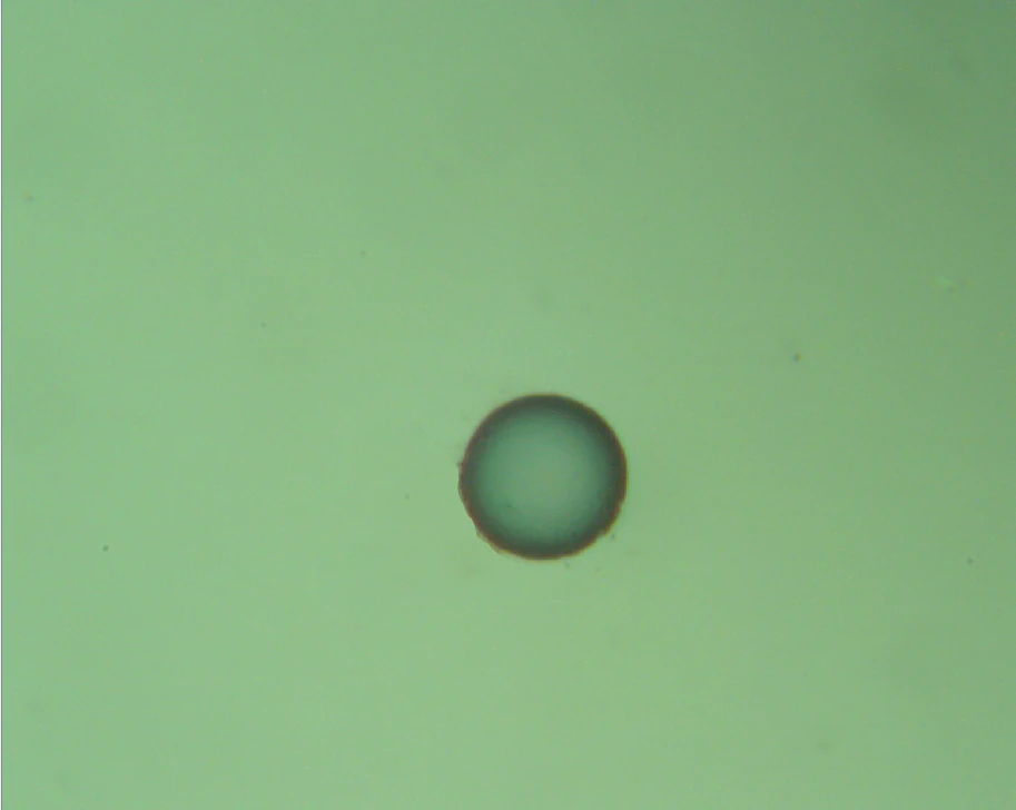
In situ microscopyEnlarge image ↗
In situ microscopy

In situ microscopy

Inspects surface morphology at high magnification without removing the sample.

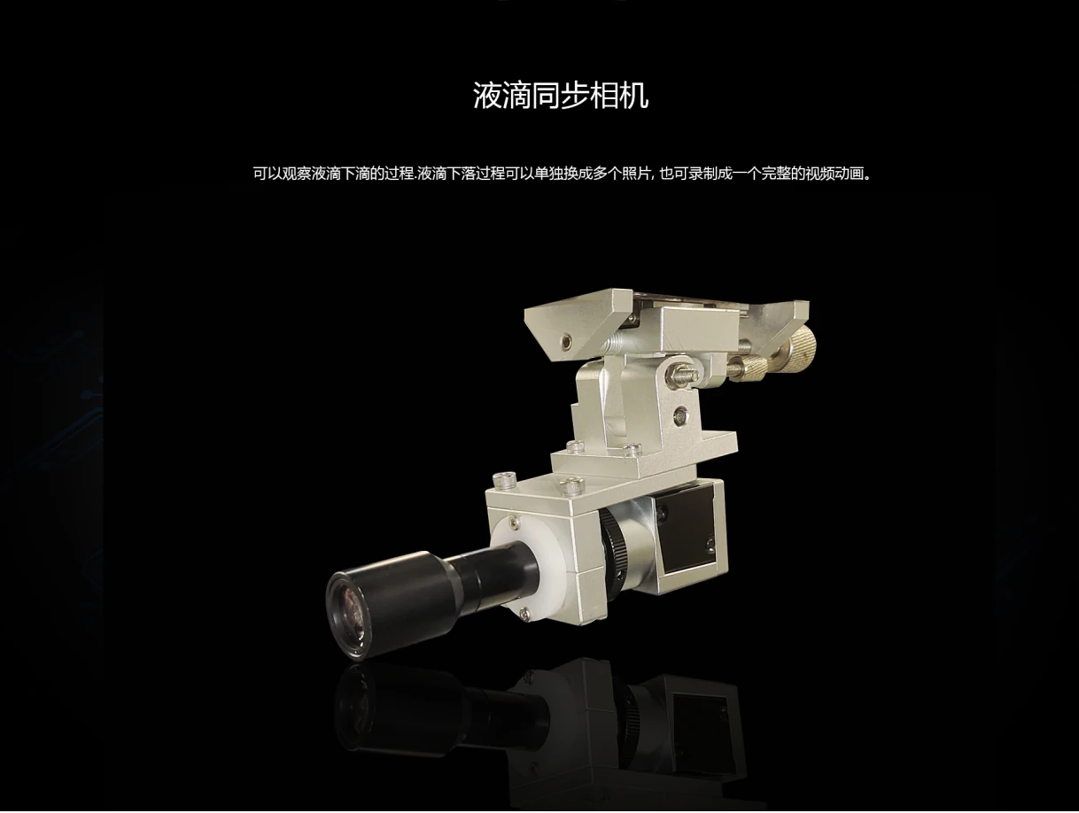
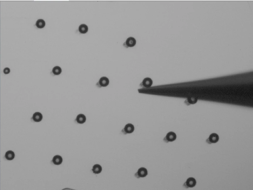
Droplet imagingEnlarge image ↗
Droplet imaging

Droplet imaging

Records droplet dynamics synchronously as images or video.

Nozzle alignment and droplet detail

Camera and printhead positioningEnlarge image ↗
Camera and printhead positioning

Camera and printhead positioning

Select the camera view required for each task. Camera and nozzle positions can be adjusted independently in X, Y and Z, with appropriate electrical clearance between the optics and printhead.

Pattern-based printing softwareEnlarge image ↗
Pattern-based printing software

Pattern-based printing software

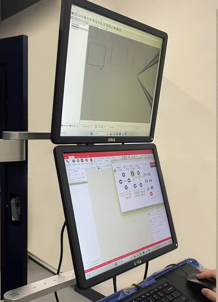
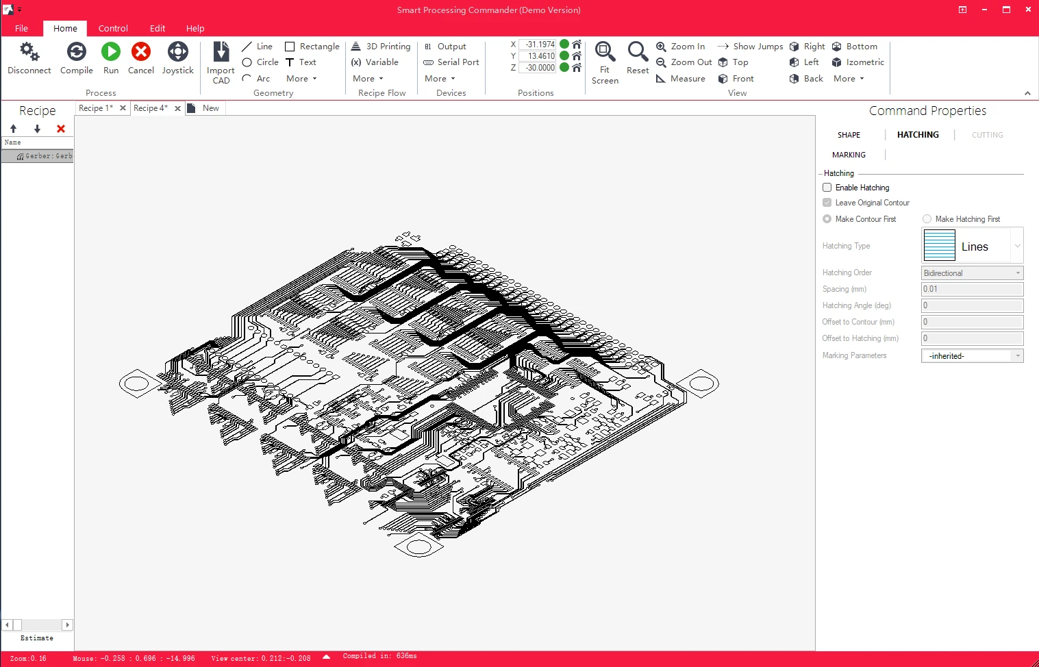
Edit patterns, view toolpaths and monitor operating status without manually writing G-code. The software generates and executes motion commands, with real-time X–Y–Z position display from closed-loop feedback.

Distance-based jetting synchronizationEnlarge image ↗
Distance-based jetting synchronization

Distance-based jetting synchronization

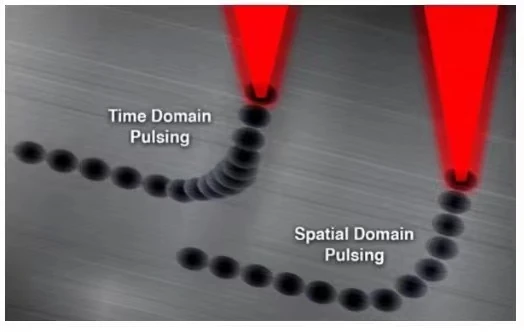
Distance-triggered jetting coordinates droplet spacing with motion speed. Corner compensation helps maintain line-width uniformity as speed changes. Path planning includes speed-based corner rounding and lead-in moves.

File import and job managementEnlarge image ↗
File import and job management

File import and job management

Import patterns, set process parameters and execute motion in one workflow. Job queues and global parameter backups support reuse and recovery after unintended changes.

Pattern sourceSupported formats
CAD drawingsDXF / DWG
Circuit layoutsGerber / NC Drill
Text dataTXT / CSV
Parametric drawing and scriptingEnlarge image ↗
Parametric drawing and scripting
Parametric drawing and scriptingEnlarge image ↗
Parametric drawing and scripting

Parametric drawing and scripting

Draw points, lines, circles, arcs, ellipses, rectangles and polylines. Add Chinese or English text, barcodes and QR codes.

Eight fill strategies include line, crosshatch, serpentine and sandwich fills. Grids, circular arrays and standard patterns support parametric editing with real-time toolpath display.

Scripting supports loops, conditional logic, variables and trigonometry, plus dimension measurement for CAD and 3D geometry.

05

Samples & videos

Layout schematicEnlarge image ↗
Layout schematic
Sample micrographsEnlarge image ↗
Sample micrographs

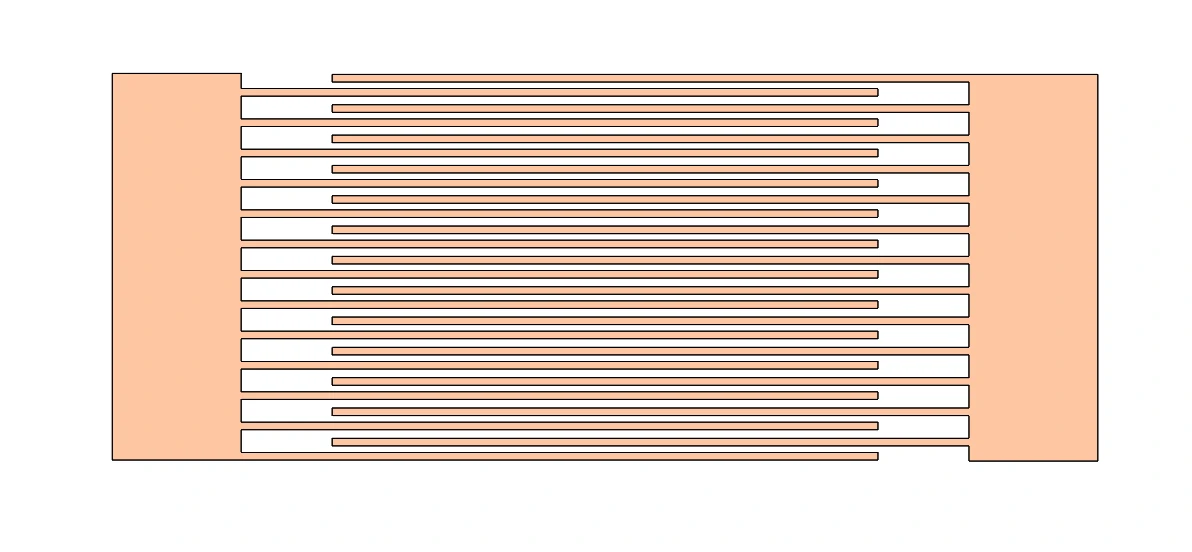
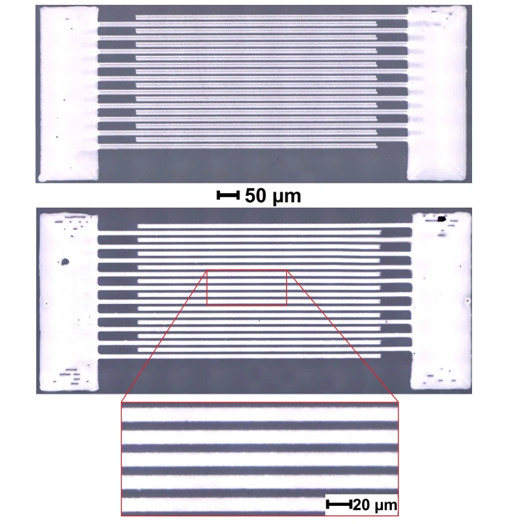
Interdigitated electrode patterns

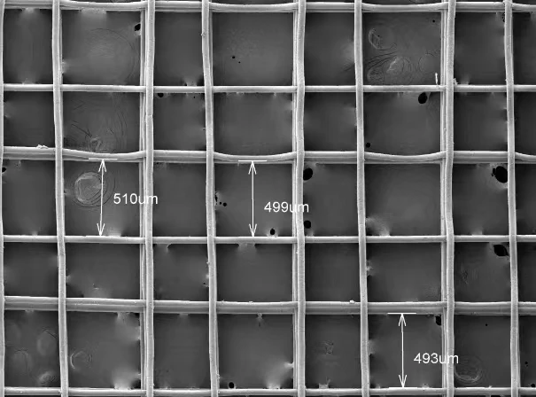
Two interleaved sets of electrode fingers are separated by gaps. The schematic and micrographs show the overall geometry and local detail. Refer to the scale bars in the images.

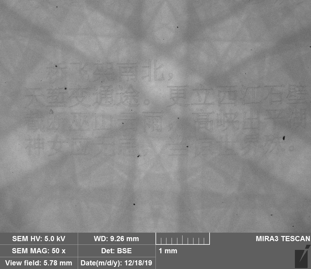
Complex text and 2D micropatternsEnlarge image ↗
Complex text and 2D micropatterns

Complex text and 2D micropatterns

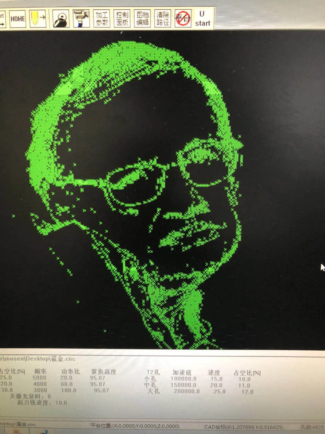
The Chinese poetry example demonstrates the conversion of dense patterns and complex strokes into executable toolpaths. Microscopic inspection reveals the overall shape, line connections and local deposition.


Continuous-line printing

Observe line continuity along serpentine paths and turns. The toolpath overlay compares the planned trajectory with deposited lines.

Dot-pattern printing

Graphics are converted into arrays of discrete droplets. Synchronized path and camera views show printing detail.

Miniature maps and complex contours

Continuous paths define curves and irregular boundaries. Compare the actual printing in the camera view with the programmed path.

06

Specifications & applications

TL-EHD key specifications

ParameterSpecification
Dot and line feature size1–45 μm. Actual feature size depends on the material and process.
High-voltage output / current0–2000 V / 0–10 mA
Nozzle diameter1–100 μm
Fluid delivery rate0.01 μL/h–99.9 mL/h
Fluid viscosity300–5000 cP
Syringe volumes1 / 10 / 20 mL
Silicon wafer sizes1, 2, 3 and 4 inches
UV curing wavelength365 nm
System dimensions1613 × 908 × 724 mm
Approximate system weight500 kg

100 nm and ±1.5 μm are stage positioning specifications. Actual print placement accuracy depends on the material and process.

Applications in microscale patterning

Research applications require processes matched to the material and geometry.

Printed electronics

Flexible circuits, thin-film transistors, touch electrodes, localized circuit repair and micro/nanoscale dispensing.

Displays and micro-optics

Display devices, quantum-dot color-conversion layers, microlenses and micro-optical structures.

Sensors and energy devices

Pressure and functional sensors, solar-cell patterning and electrodes for microscale energy storage.

Biomaterials and 3D structures

Research in 3D micro/nanostructure printing, tissue-engineering scaffolds and biomaterials, including cell printing.

Interdigitated and functional electrodes

Fine electrode patterns for sensing, acoustic and electronic devices.

Tell us what you want to make.

Share your material, target structure and sample size. We can discuss a suitable platform and configuration.

Discuss your application