TONGLI

TL-Ultra

Flagship benchtop electrospinning system

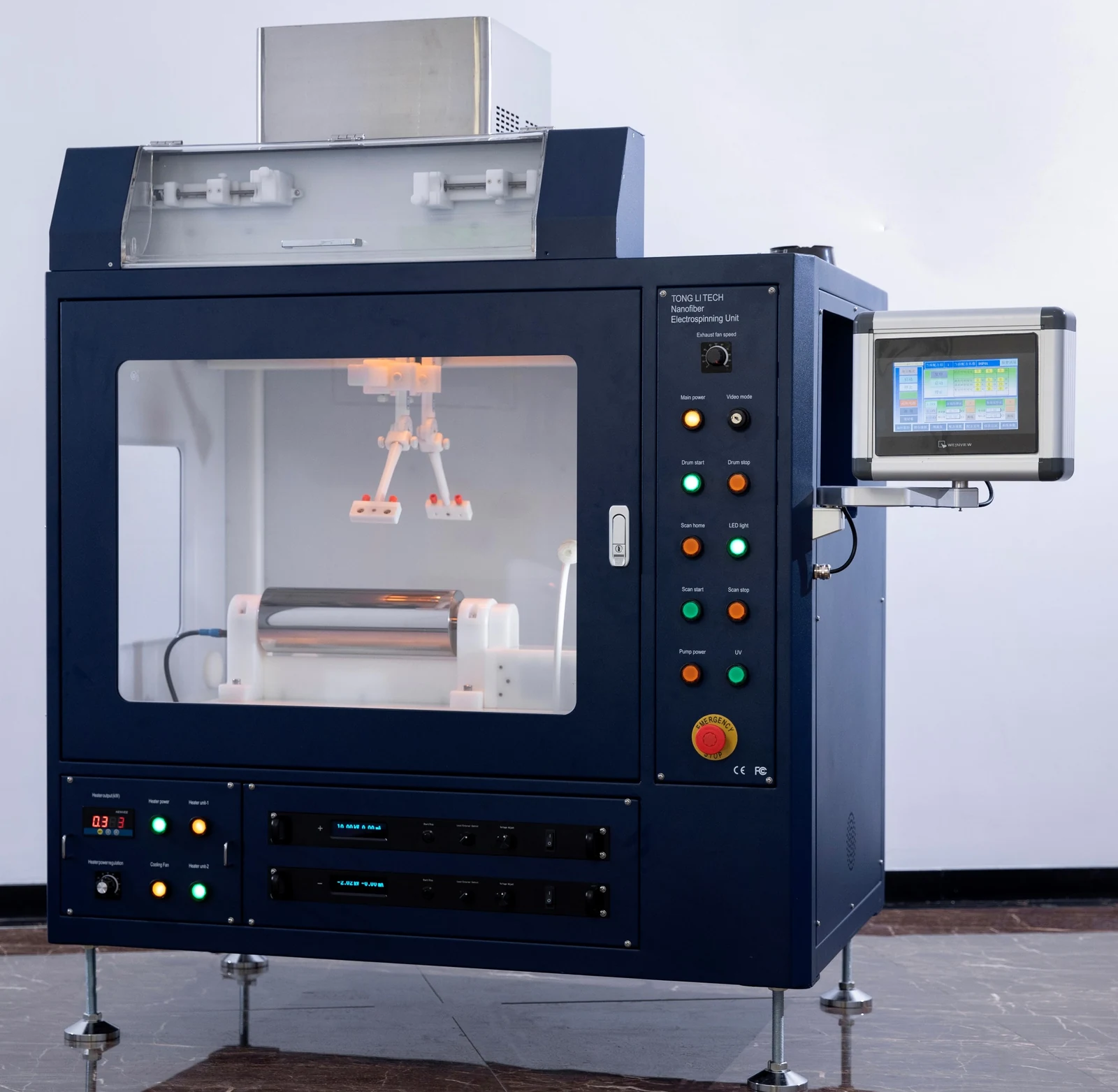
Four independent feed channels, versatile spinnerets and more than 30 collector combinations. Develop composite fibers, nanofiber membranes, continuous yarns and porous 3D structures on Tongli’s most extensively equipped benchtop laboratory platform.

TL-UltraEnlarge image ↗
TL-Ultra
4
Independent feed channels
4
V-arranged needles
30+
Collector combinations
10″
Touchscreen control

Choose the spinnerets, collectors and process modules for your application. The configurations shown here are available choices; they are not all supplied together. Optional upgrades are identified below.

01

Platform overview

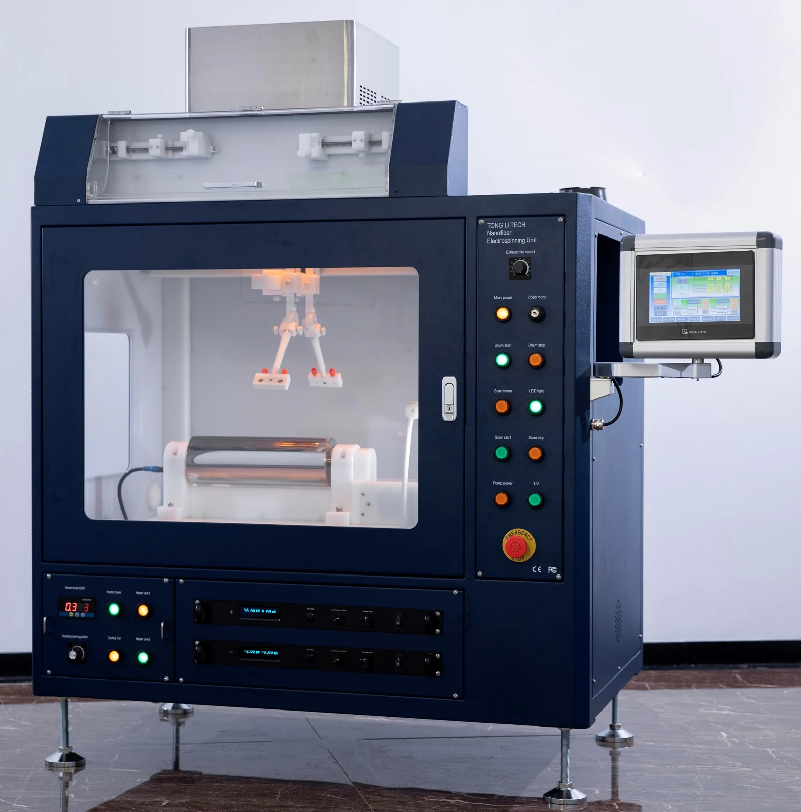
Built for flexible laboratory workEnlarge image ↗
Built for flexible laboratory work

Built for flexible laboratory work

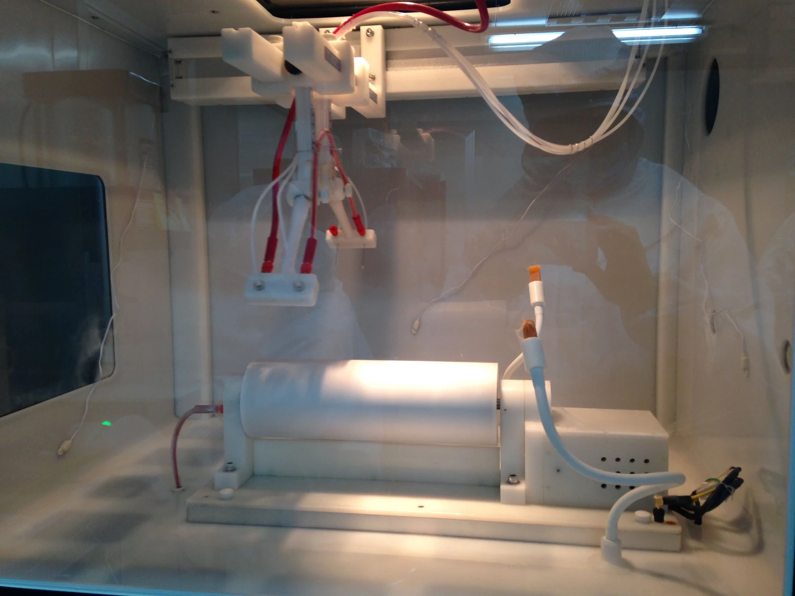
  • A corrosion-resistant coated metal enclosure has insulated inner walls and accessible surfaces for cleaning. Windows on two sides make the process visible.
  • External components reduce electric-field interference. Inlet and exhaust openings support uniform airflow, with chamber lighting and temperature/humidity displays. A 10-inch touchscreen and quick-access buttons bring the main controls together.

Key specifications

Bipolar HV configuration±30–50 kV
Pump channels4 independent servo-driven channels; optional 6–8 channels
Touchscreen10″
Motorized X travel400 mm
Linear speed1–40 mm/s
Chamber heatingAmbient to 45°C
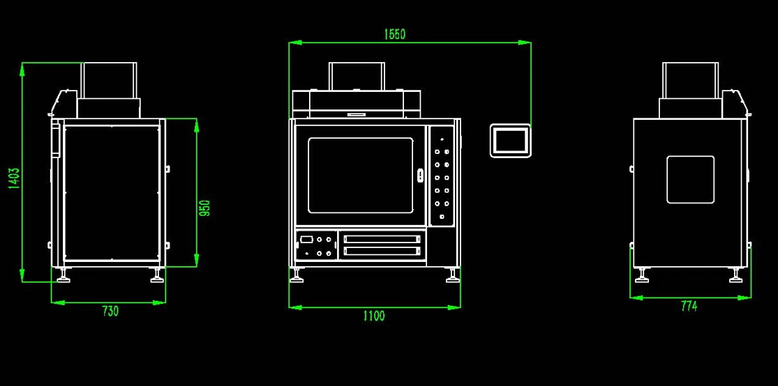
Enclosure, W × D × H1100 × 730 × 950 mm
Overall height1403 mm
02

Control & environment

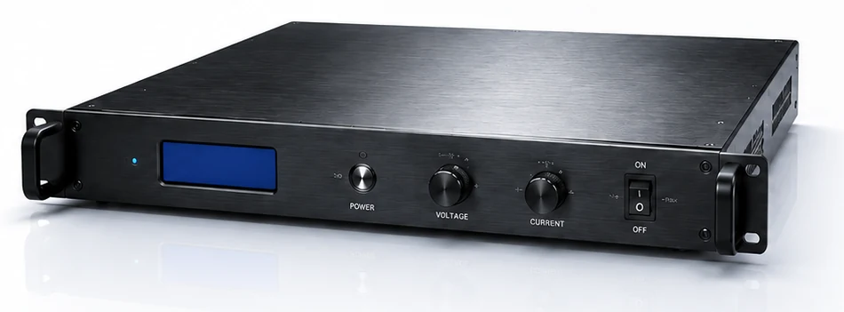
Bipolar high-voltage suppliesEnlarge image ↗
Bipolar high-voltage supplies

Bipolar high-voltage supplies

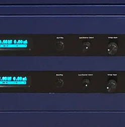
  • One negative high-voltage supply and multiple positive supplies support bipolar configurations. Automatic voltage compensation and real-time monitoring help maintain stable output.
  • Touchscreen and quick-access controls work with industrial-grade insulation. Protection covers overvoltage, overcurrent, arcing and short circuits.
Bipolar HV configuration±30–50 kV
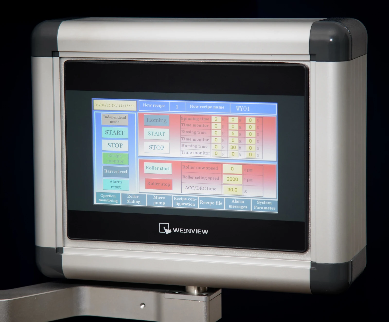
Integrated touchscreen controlEnlarge image ↗
Integrated touchscreen control

Integrated touchscreen control

  • Control high voltage, syringe pumps, spinneret motion and the rotating collector from one interface. Adjust parameters during operation, record data and coordinate motion.
  • The screen can be stowed at the side of the enclosure.
Touchscreen10″
Four-channel servo syringe pumpEnlarge image ↗
Four-channel servo syringe pump

Four-channel servo syringe pump

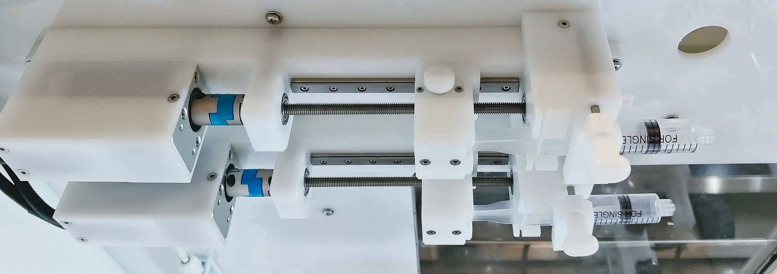
  • Four independent channels let you set each plunger speed separately for multicomponent experiments. Servo drives provide high thrust for viscous liquids, with electrical isolation for high-voltage operation.
  • Install the pump inside or outside the enclosure to suit the process. An upgrade to 6–8 channels is available.
DehumidificationEnlarge image ↗
Dehumidification

Dehumidification

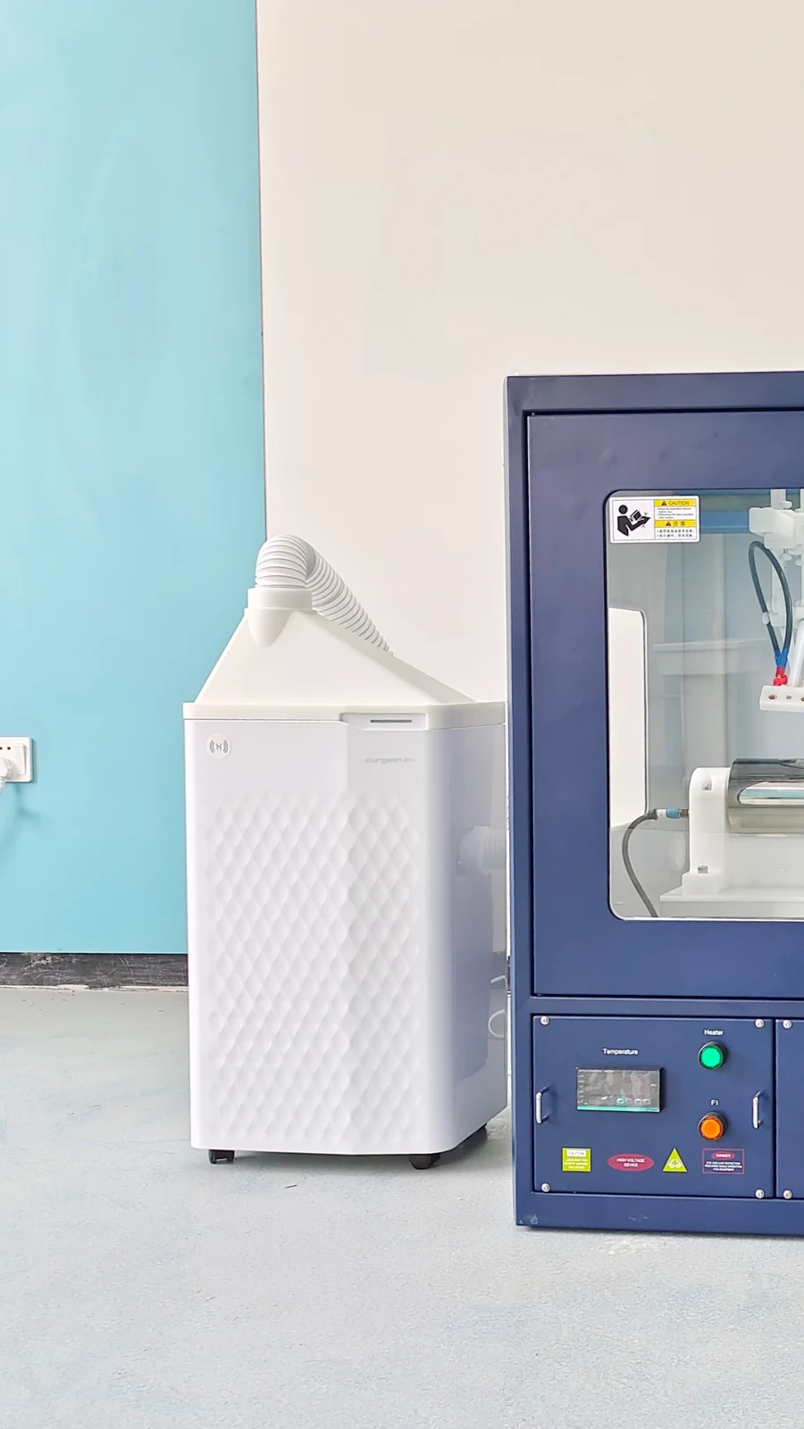
  • A compact compressor delivers a gentle flow of dry air. The standard dehumidifier reaches approximately 30% RH at room temperature.
  • An enhanced dehumidifier reaching approximately 20% RH is available at extra cost.
Optional mist-free humidifierEnlarge image ↗
Optional mist-free humidifier

Optional configuration

Optional mist-free humidifier

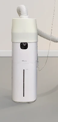
  • Evaporative humidification maintains uniform chamber humidity while reducing droplet deposition on the collector. Quiet, energy-efficient operation with germicidal protection.
Humidity range50–80% RH
Dimensions, W × D × H214 × 214 × 545 mm
External chamber heatingEnlarge image ↗
External chamber heating

External chamber heating

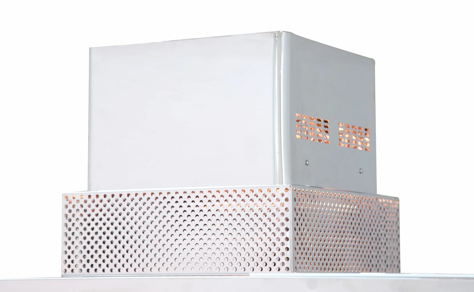
  • An external visible-light heat source provides uniform heating over a large area, with adjustable output. Keeping the heater outside avoids internal dust-trapping structures and electric-field interference.
  • An optional collector heating plate can provide additional heat.
Chamber heatingAmbient to 45°C
Heated mandrel, maximumEnlarge image ↗
Heated mandrel, maximum
Heated drum, maximumEnlarge image ↗
Heated drum, maximum

Optional configuration

Independent collector heating

  • Heat the mandrel and drum independently for low-volatility solvents, specialty materials and thermally assisted electrospinning.
Heated mandrel, maximumApprox. 60°C
Heated drum, maximumApprox. 140°C
03

Spinnerets & motion

Interchangeable spinnerets support low-volume experiments and multicomponent fibers. Each uses a dedicated insulating holder and intelligent motion control, with positions that can be recorded for repeatable setups.

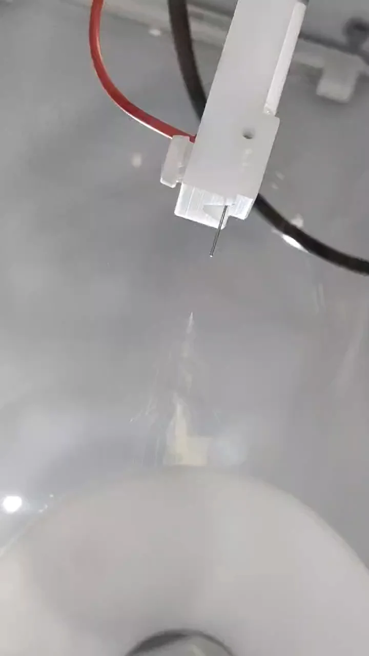
Single-needle spinneretEnlarge image ↗
Single-needle spinneret

Single-needle spinneret

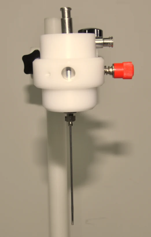
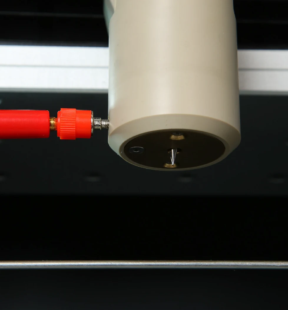
  • Includes 100 stainless-steel needles in various sizes. The dedicated holder accepts standard metal needles and allows adjustment of the spinning angle and spinneret-to-collector distance.
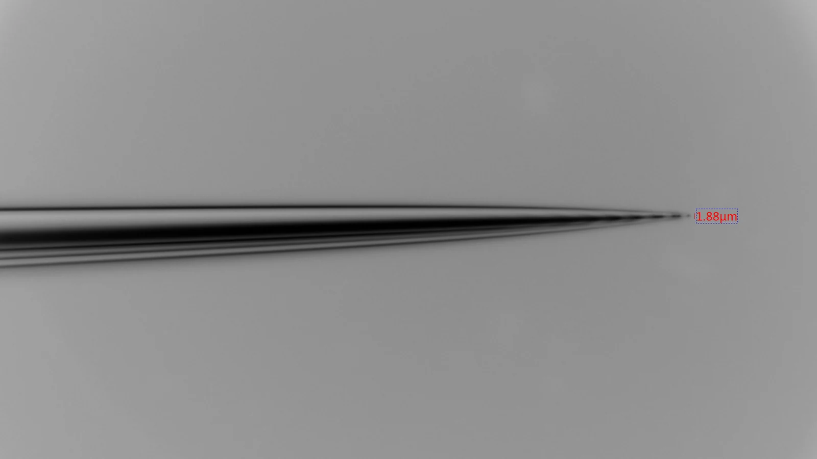
Glass microcapillary needlesEnlarge image ↗
Glass microcapillary needles
Glass microcapillary needlesEnlarge image ↗
Glass microcapillary needles

Glass microcapillary needles

  • Hollow glass needles are available in diameters from 1 to 45 µm, with a minimum inner diameter of 1 µm. Small bores support low-viscosity fluids and low-volume delivery for ultrafine fibers and near-field direct writing.
Tubeless, low-volume spinneretsEnlarge image ↗
Tubeless, low-volume spinnerets

Tubeless, low-volume spinnerets

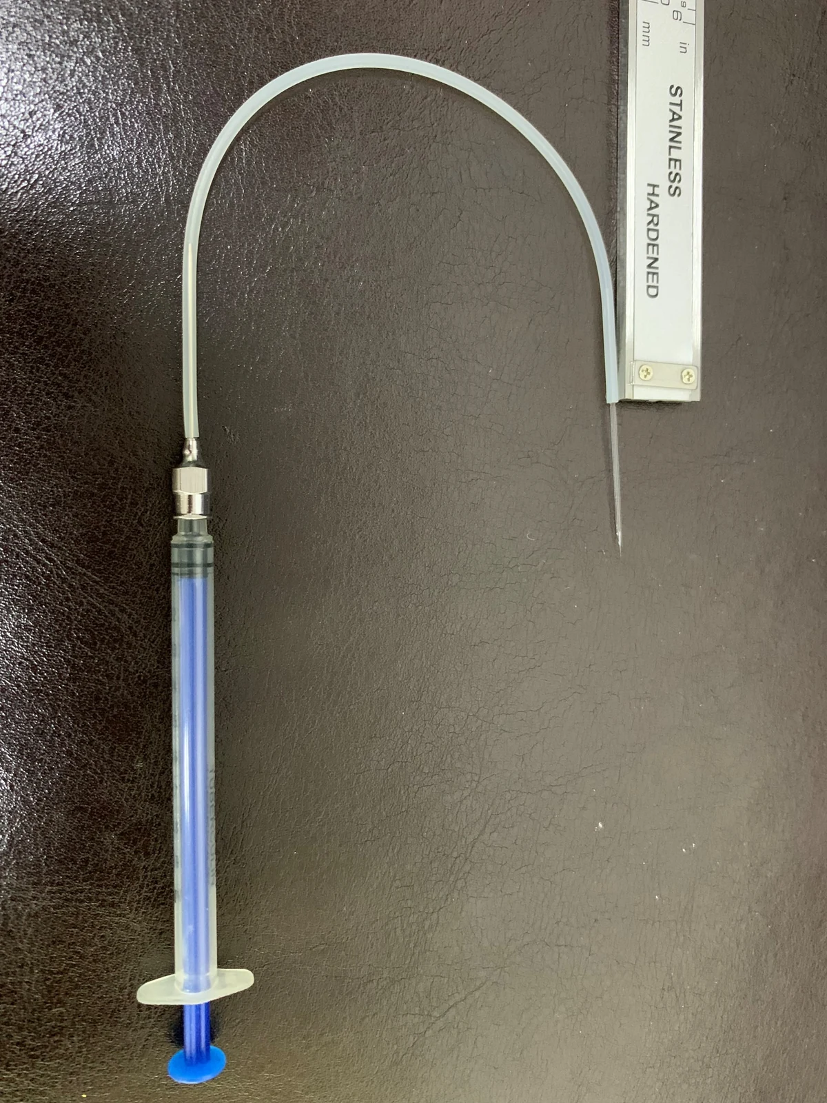
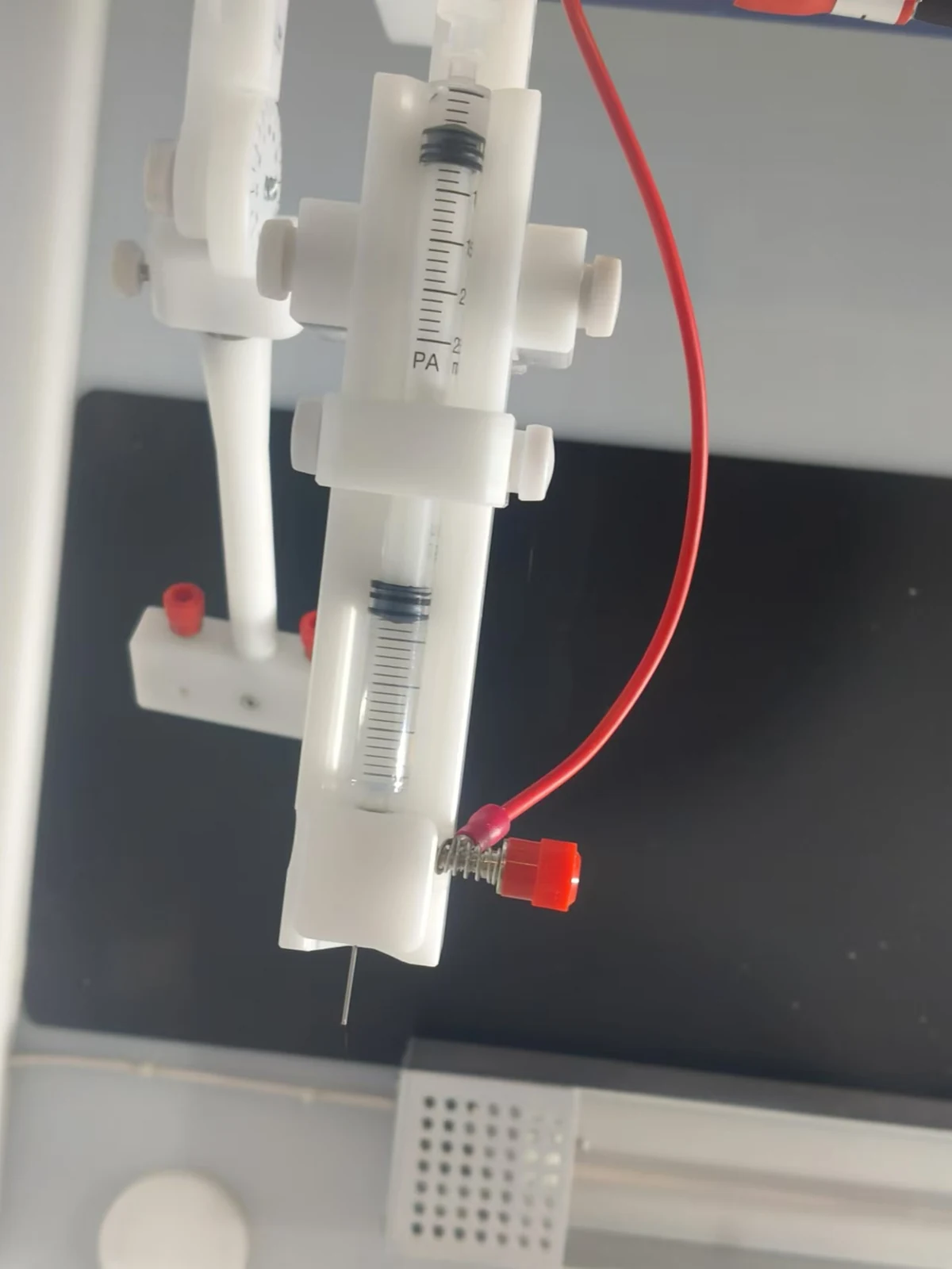
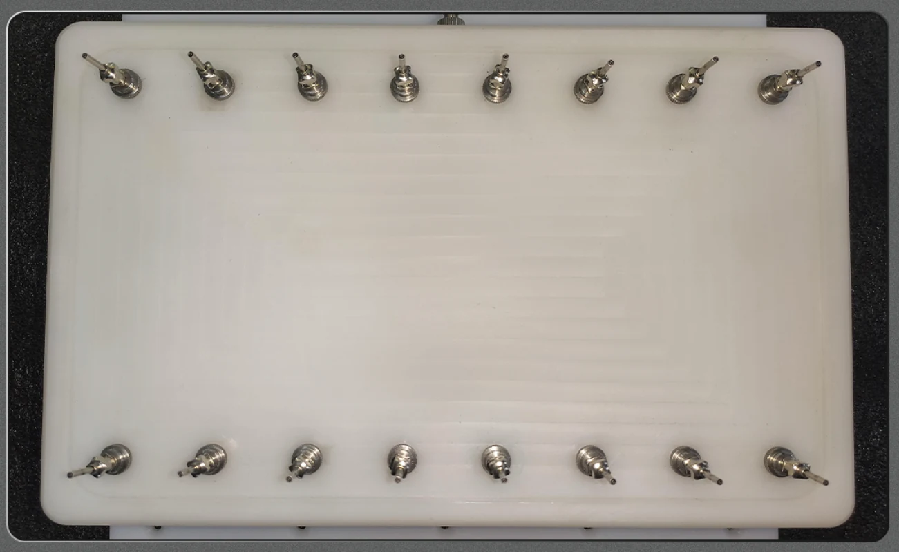
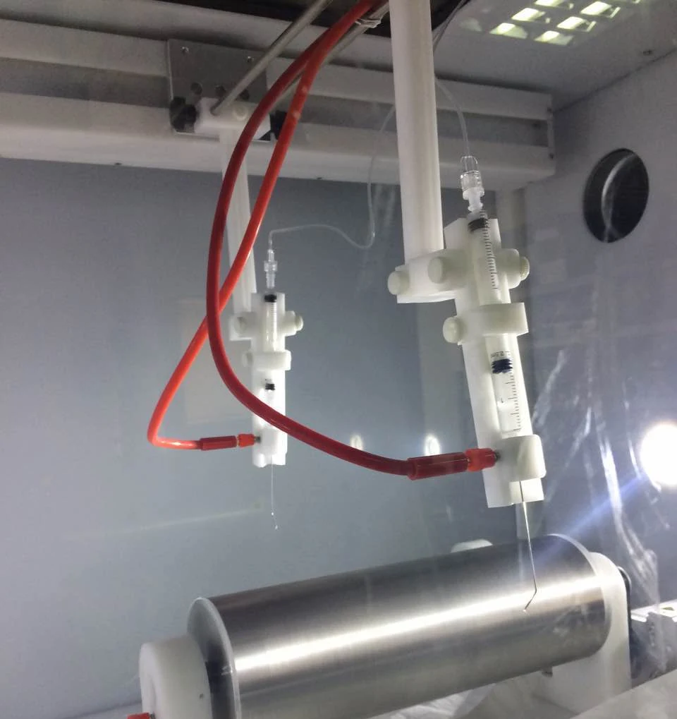
  • The syringe connects directly to the needle, reducing tubing consumables and using as little as 0.5 mL of solution per experiment.
  • Two tubeless spinnerets are included in the standard configuration. Additional units are optional, with configurations for 2–4 simultaneous spinnerets.
Coaxial needle kitEnlarge image ↗
Coaxial needle kit
Concentric needle tipEnlarge image ↗
Concentric needle tip

Coaxial spinneret

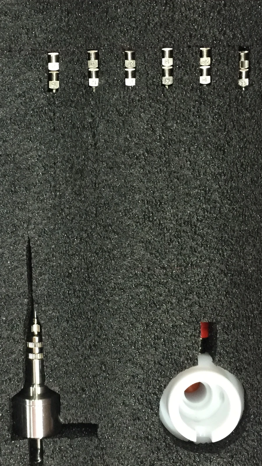
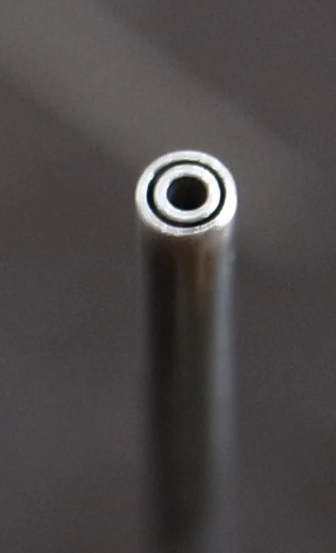
  • Five needle sets offer interchangeable inner and outer needles for core–shell fibers. Concentric construction and an extended tip reduce the required spinning voltage.
  • Independent inner and outer fluid feeds use two pump channels. The spinneret also supports gas-assisted spinning.
Coaxial multi-needle arraysEnlarge image ↗
Coaxial multi-needle arrays
Coaxial multi-needle arraysEnlarge image ↗
Coaxial multi-needle arrays

Optional configuration

Coaxial multi-needle arrays

  • Coaxial needles are available in circular and array layouts as optional configurations.
Triaxial spinneretEnlarge image ↗
Triaxial spinneret
Concentric needle tipEnlarge image ↗
Concentric needle tip

Triaxial spinneret

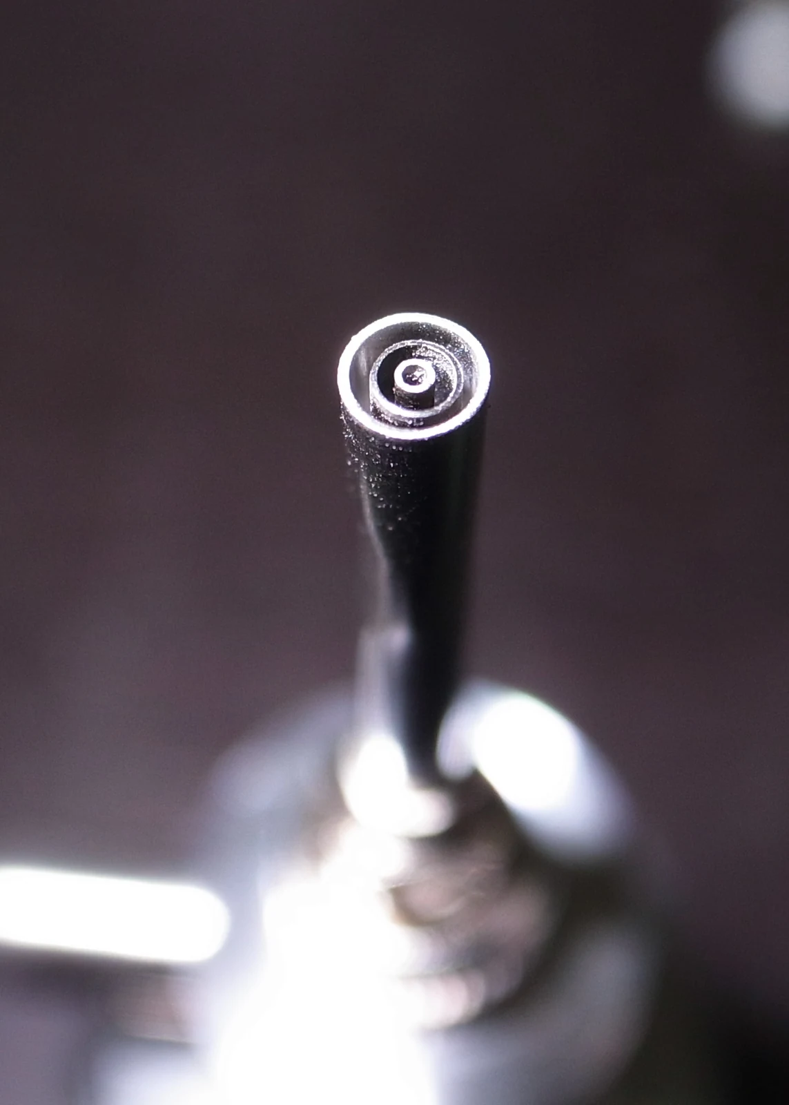
  • Five needle sets with interchangeable inner, middle and outer needles produce three concentric layers. Extended needle geometry reduces the required spinning voltage.
  • Three independent pump channels feed the fluids separately. The spinneret is also compatible with gas-assisted spinning.

Coaxial and triaxial needle combinations

Coaxial values are needle gauges. Triaxial values are the size numbers used in the product specification, not diameters in millimeters.

Coaxial needles — gauge (G)
InnerOuter
20G14G
14G10G
21G15G
15G11G
22G16G
16G12G
23G17G
17G13G
24G18G
18G14G
26G19G
19G15G
Triaxial needles — size No.
InnerMiddleOuter
4.5916
4816
4916
5916
41220
71220
4.51220
61625
51625
92030
V-shaped four-needle systemEnlarge image ↗
V-shaped four-needle system

V-shaped four-needle system

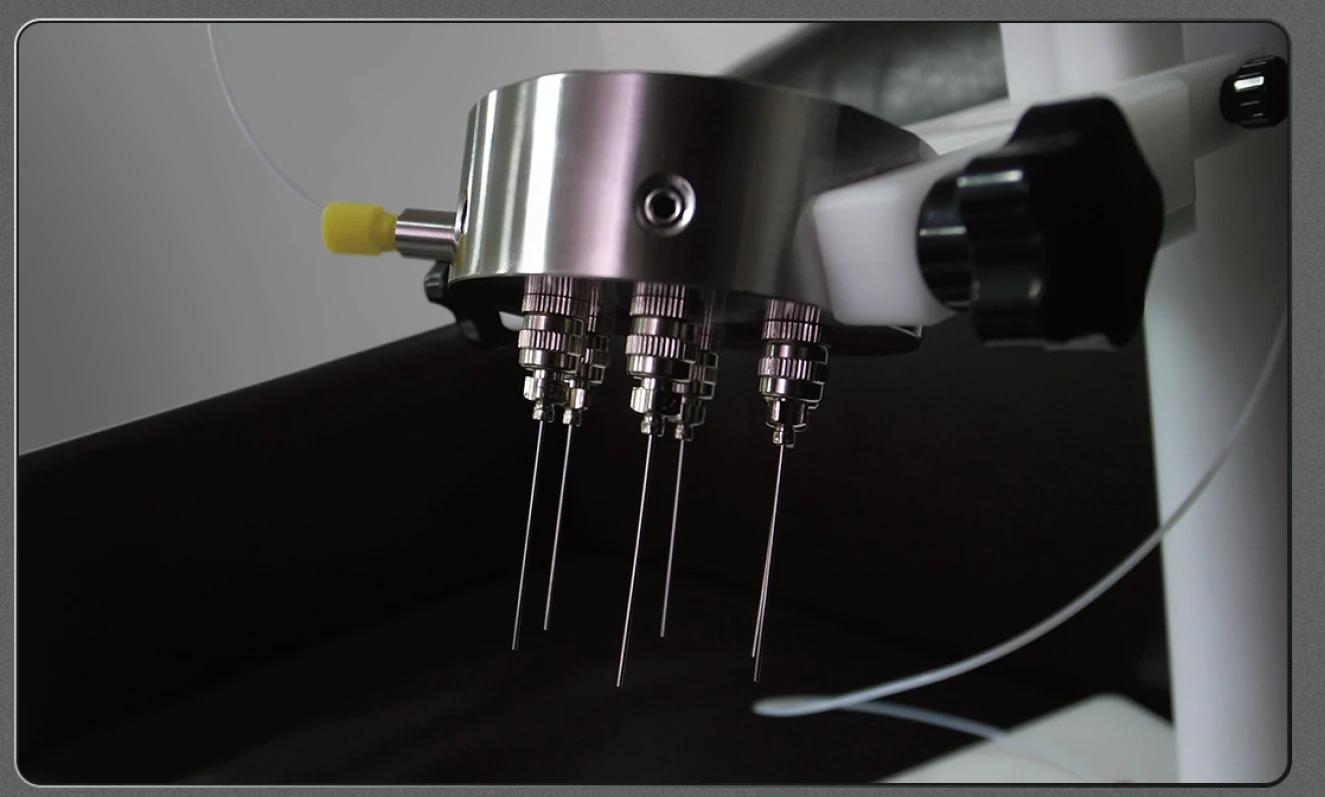
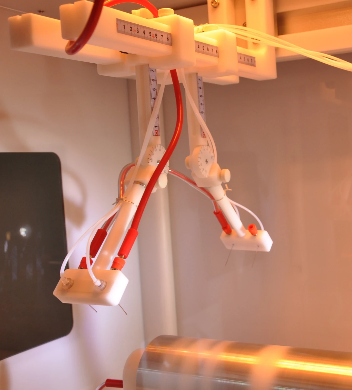
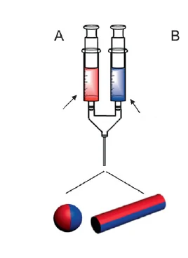
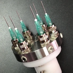
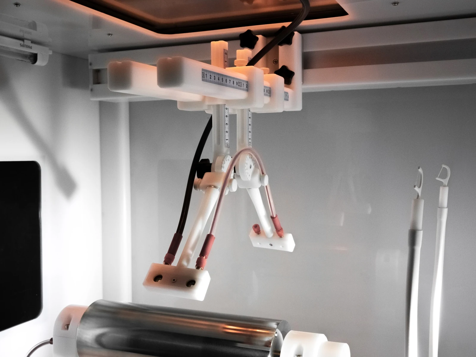
  • The four-needle platform can be configured with 4–8 V-arranged needles. Needles within each group share the same voltage; the two groups connect to opposite polarities.
  • Run electrospinning and electrospraying simultaneously, or combine different materials. Angle and distance adjustments have scales for recording positions.
Conjugate electrospinningEnlarge image ↗
Conjugate electrospinning

Conjugate electrospinning

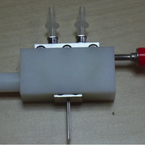
  • Two parallel needles connect to positive and negative high-voltage supplies. Opposite-polarity jets reduce residual charge at the collector for denser fiber mats.
  • Spin two different materials for composite mats, nanofiber yarns and specialty structures.
Multi-channel sea-island spinneretEnlarge image ↗
Multi-channel sea-island spinneret

Multi-channel sea-island spinneret

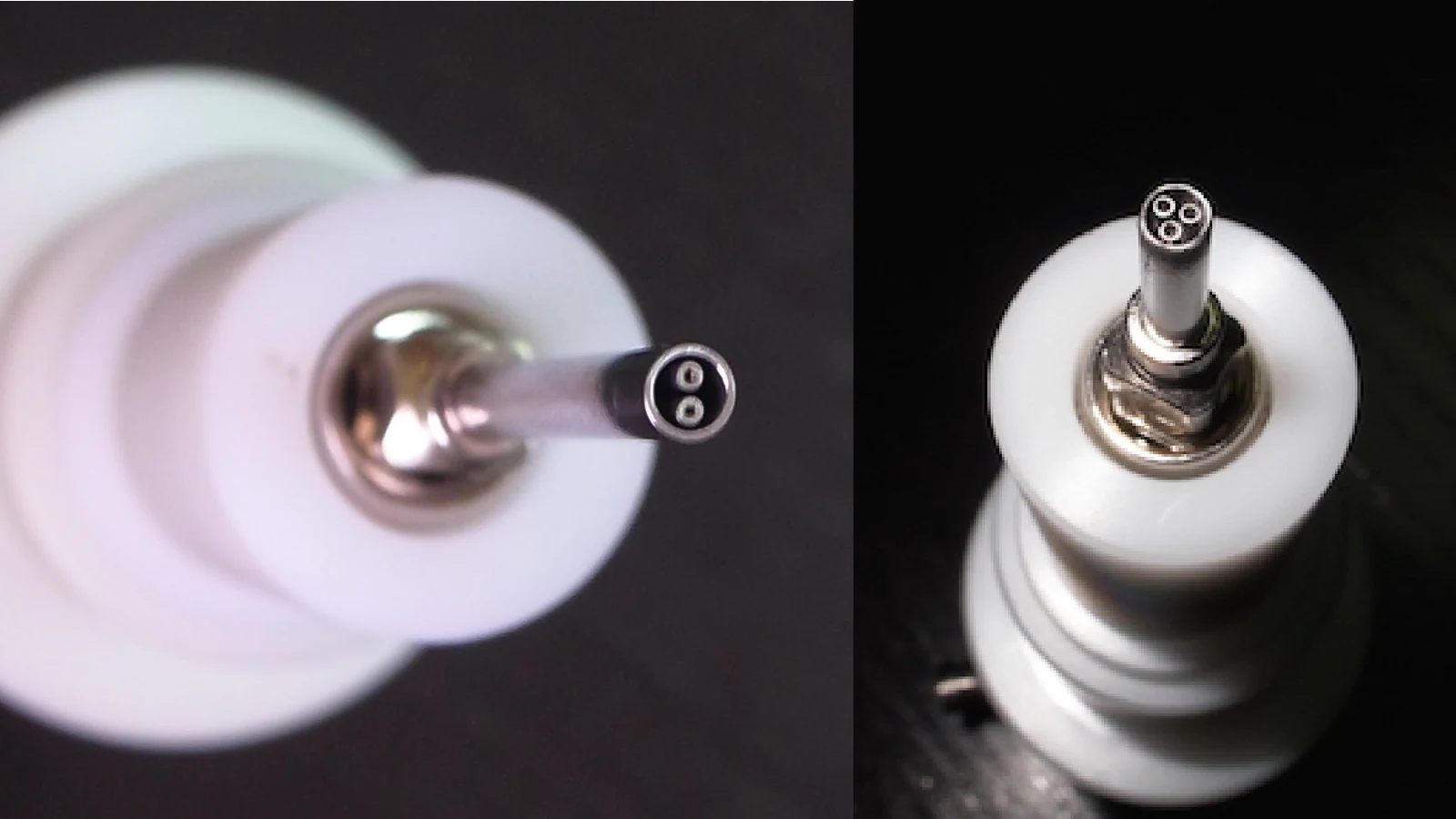
  • Two- or three-channel configurations provide independent material feeds for composite fibers with three or more components. Create sea-island, cable-like and other specialty cross-sections.
Side-by-side spinneretEnlarge image ↗
Side-by-side spinneret
Two-channel fiber formationEnlarge image ↗
Two-channel fiber formation

Side-by-side spinneret

  • Two independent channels deliver different materials for bicomponent fiber membranes. Five needle sets provide different sizes.
  • Differences in the elastic modulus of the materials can produce self-crimping, spring-like and other fiber shapes.
Linear arrangementEnlarge image ↗
Linear arrangement
Ring arrangementEnlarge image ↗
Ring arrangement
Needle arrayEnlarge image ↗
Needle array

Optional configuration

Optional multi-needle arrays

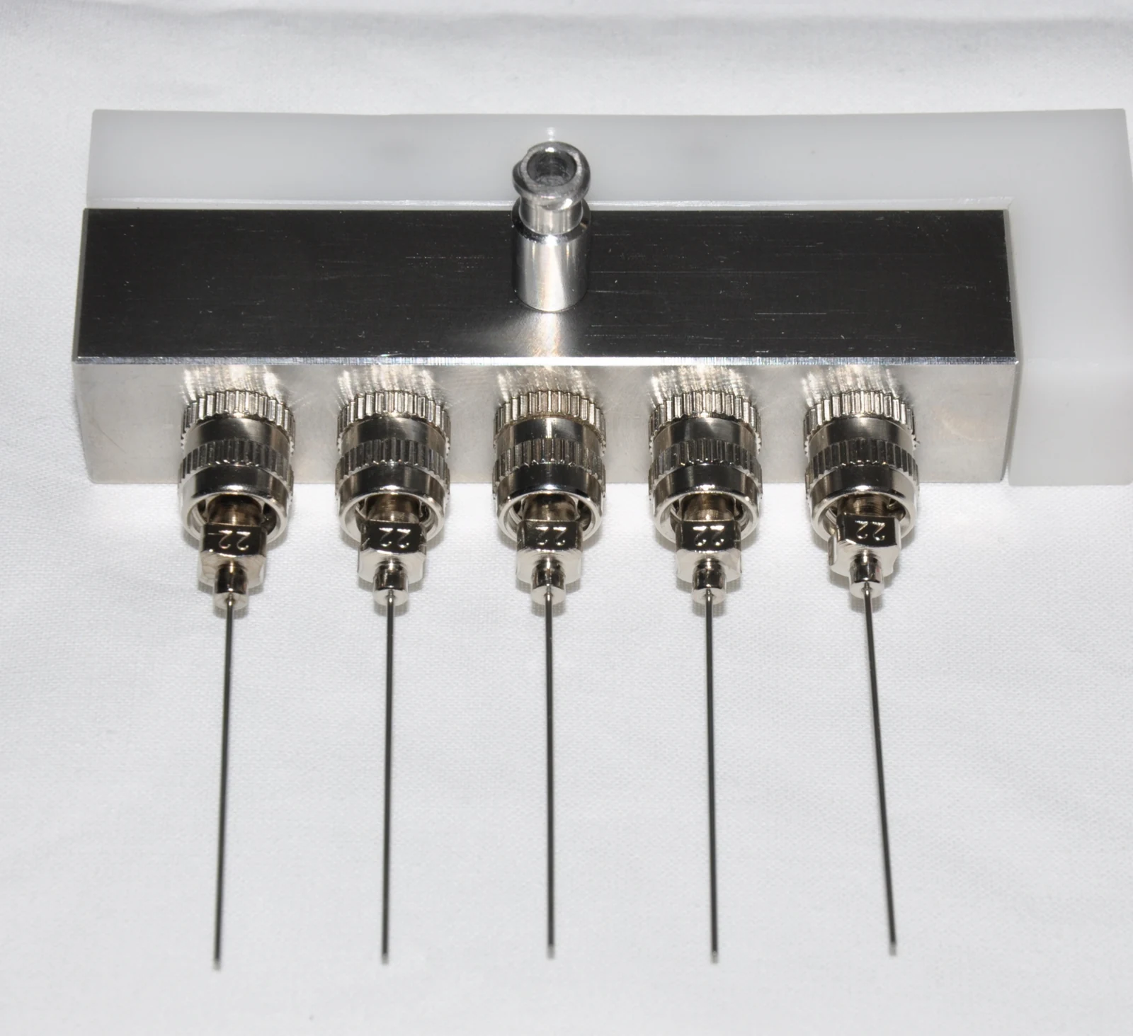
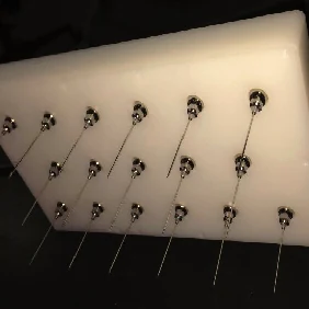
  • A single inlet distributes fluid to multiple needles for higher throughput. Choose a linear, ring or array layout.
Automatic needle cleaningEnlarge image ↗
Automatic needle cleaning

Automatic needle cleaning

  • Clean needles during operation without stopping the process, particularly when using volatile solvents. Set the cleaning frequency according to solvent evaporation. Available for the spinneret types described above.
Spinneret motion and positioningEnlarge image ↗
Spinneret motion and positioning

Spinneret motion and positioning

  • Motorized X motion traverses the spinneret along the drum axis, controlled through the touchscreen with data recording. Manual Y and Z adjustments have graduated scales.
Motorized X travel400 mm
Linear speed1–40 mm/s
04

Fiber collectors

Choose from more than 30 collector combinations for flat membranes, tubular structures and rigid substrates. Match the collection geometry and speed to the required fiber arrangement.

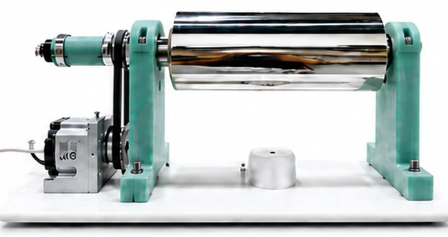
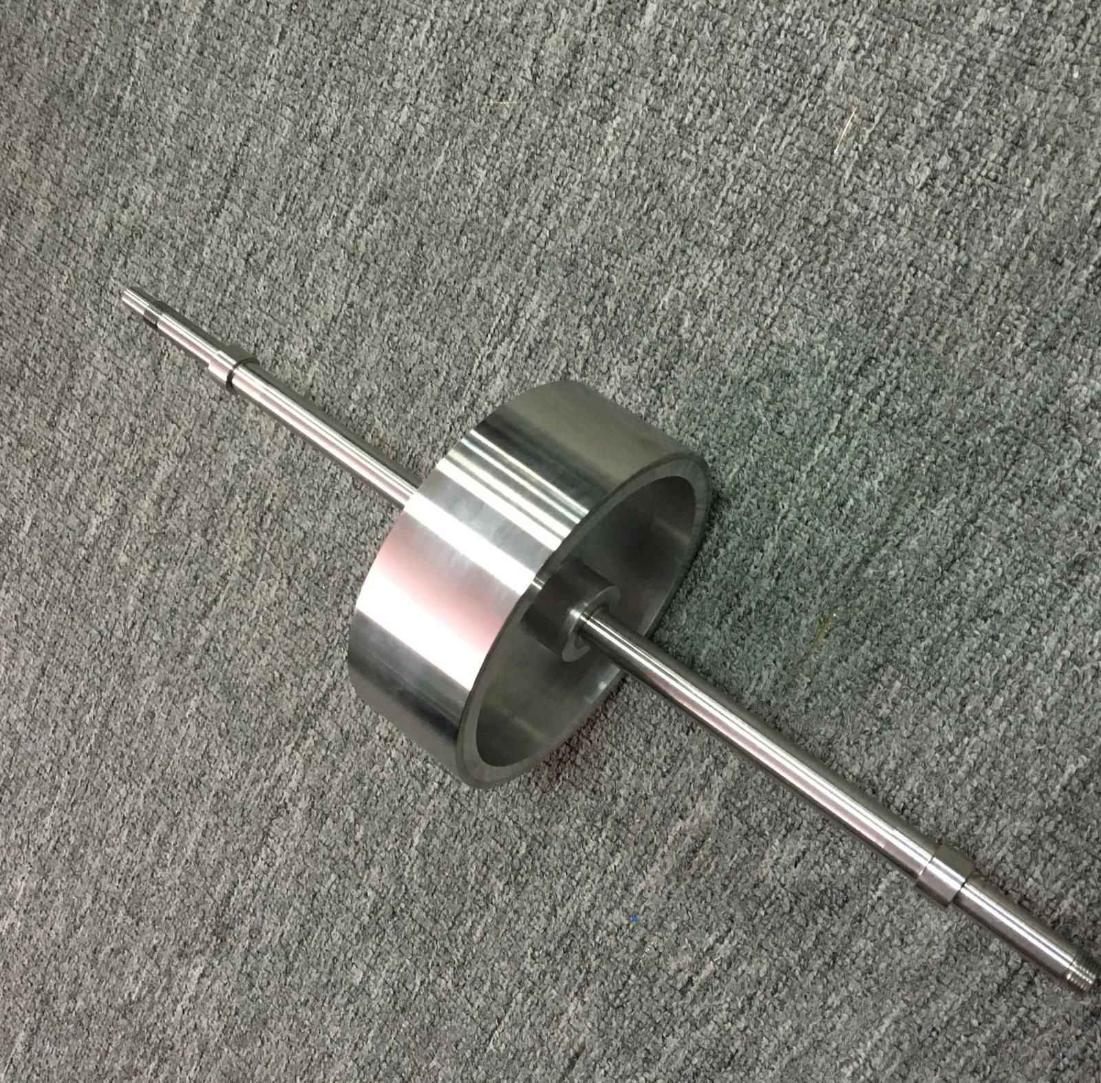
Rotating drum collectorEnlarge image ↗
Rotating drum collector
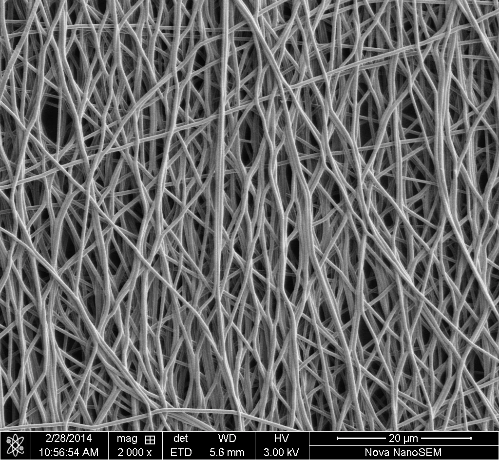
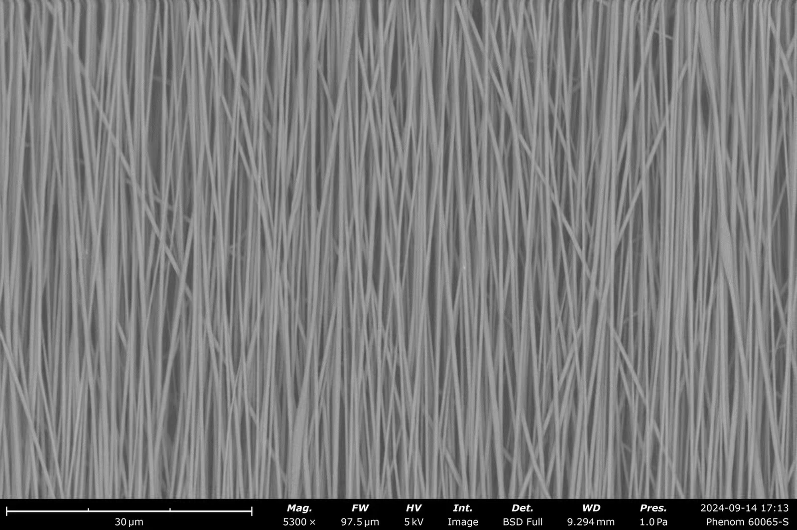
Aligned fibers — SEMEnlarge image ↗
Aligned fibers — SEM
Random fibers — SEMEnlarge image ↗
Random fibers — SEM

Rotating drum collector

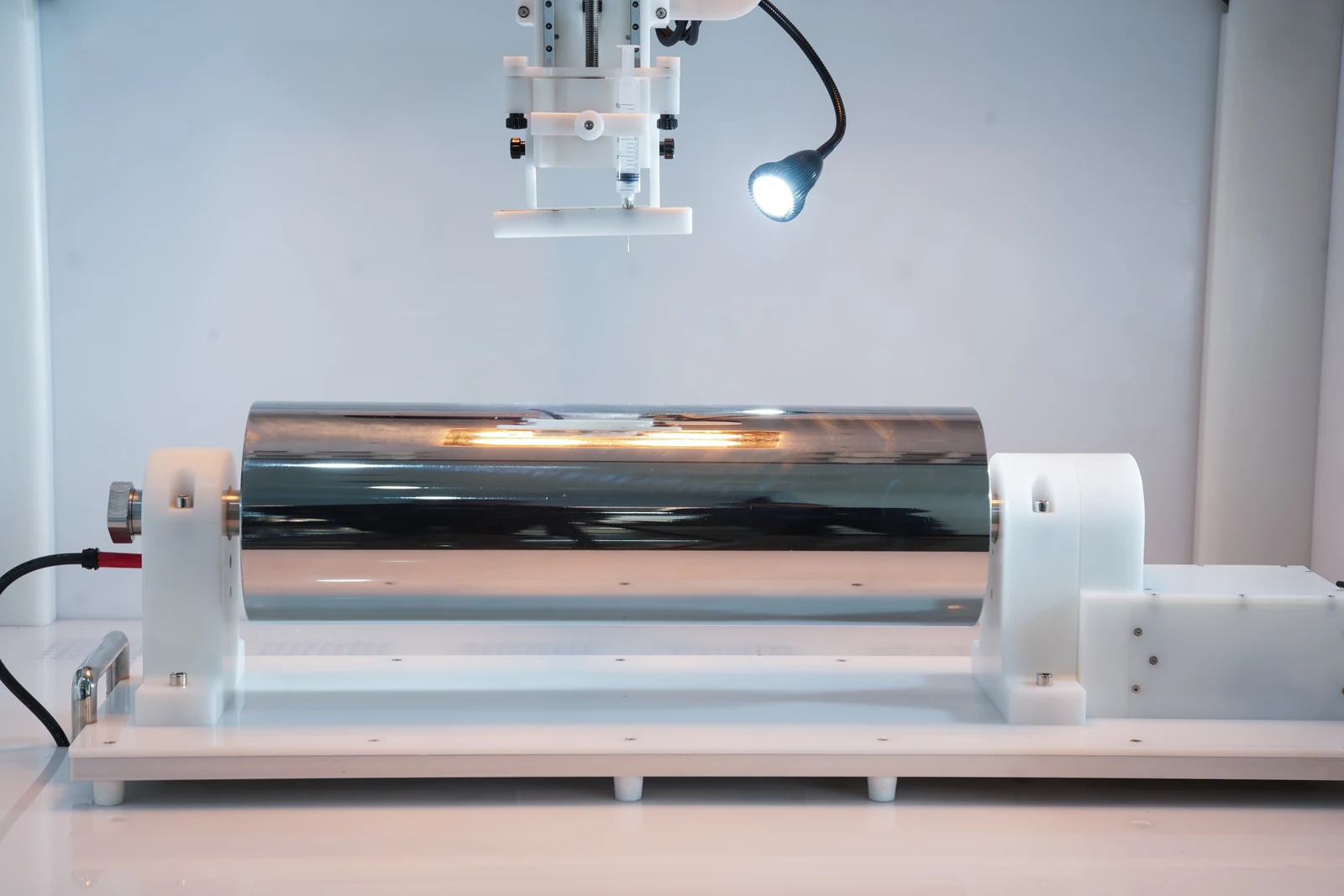
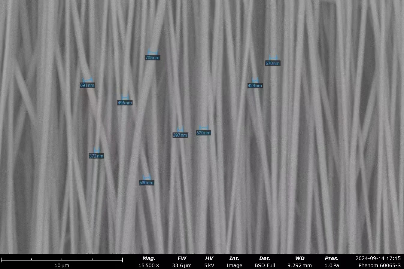
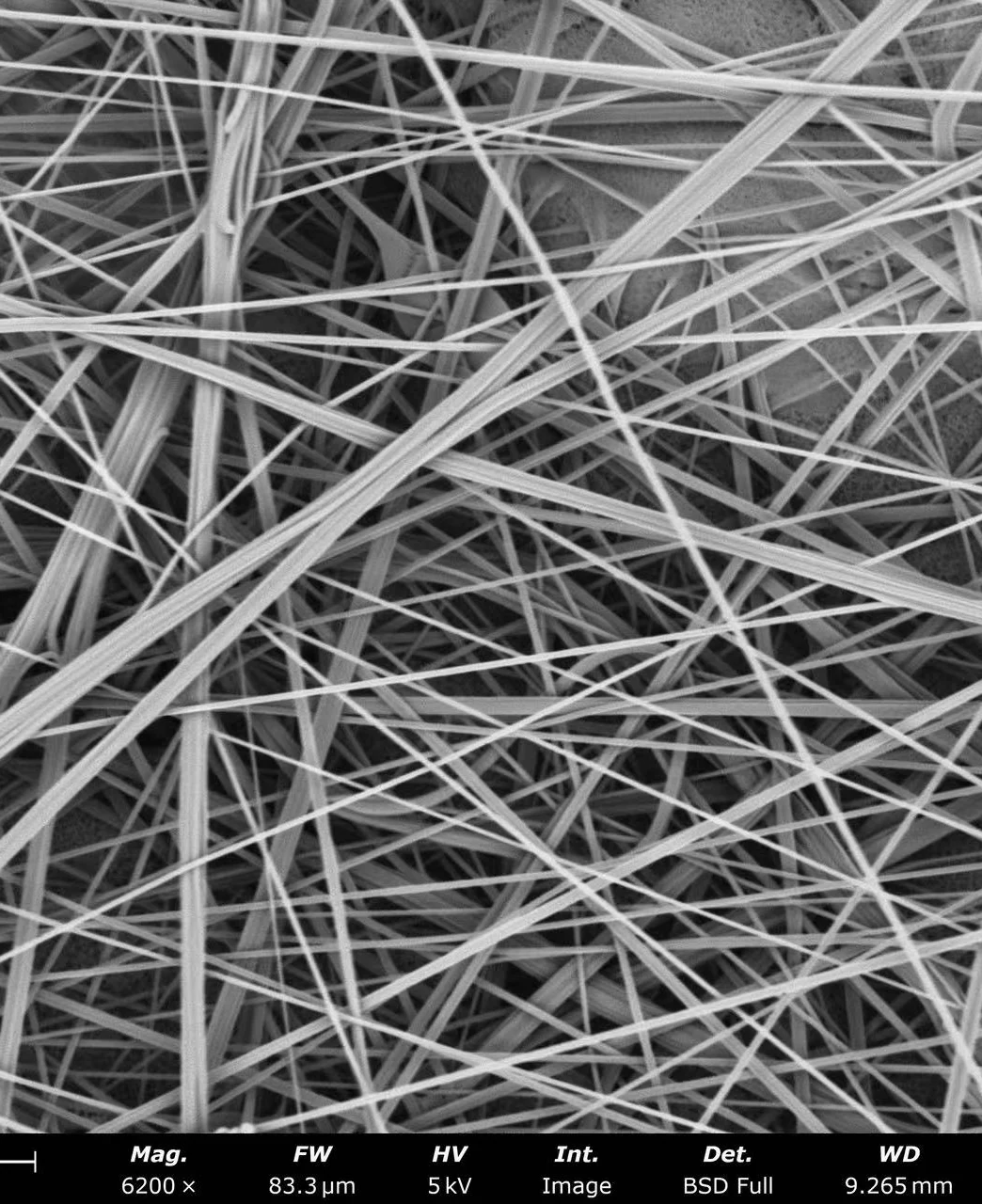
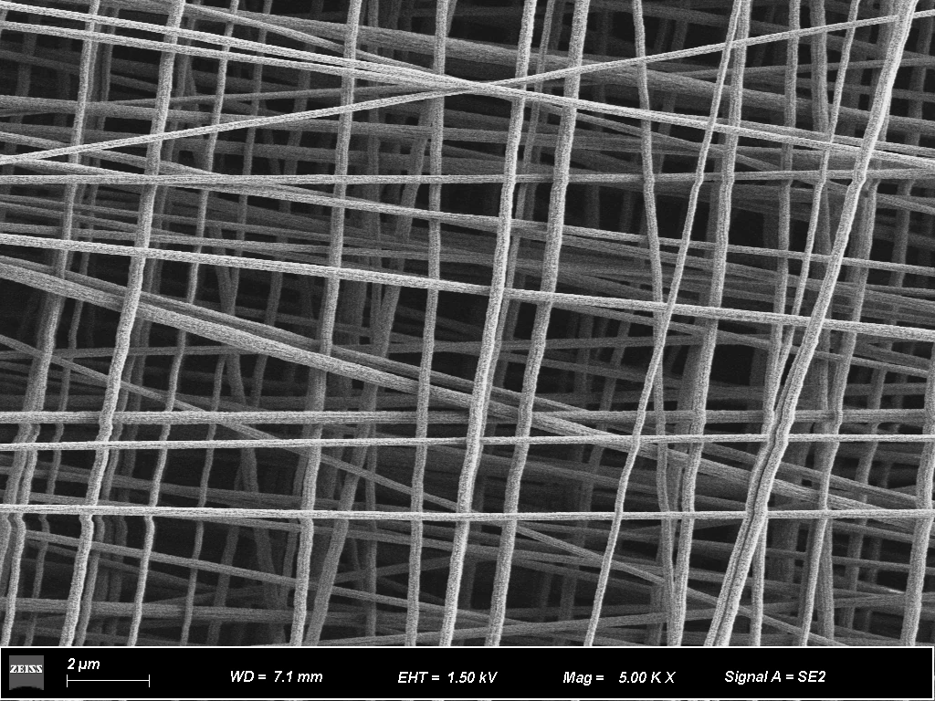
  • Collect flat membranes with random or aligned fibers. Higher rotation speeds support aligned deposition; the microscopy images show fiber morphologies.
Rotation speed1–5000 rpm
Speed accuracy±1 rpm
Diameter100 mm
Length300 mm
Unwrapped mat size300 × 314 mm
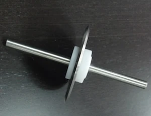
Rotating disc collectorEnlarge image ↗
Rotating disc collector
Aligned fibers — SEMEnlarge image ↗
Aligned fibers — SEM

Rotating disc collector

  • Collect narrow ribbons of highly aligned nanofibers on the disc edge. Sharp-edge and flat-edge configurations are available.
Rotation speed1–5000 rpm
Speed accuracy±1 rpm
Diameter140 mm
Unwrapped ribbon length439 mm
Highly aligned fiber collectorEnlarge image ↗
Highly aligned fiber collector

Highly aligned fiber collector

  • High-speed rotation aligns fibers into narrow, flat membranes and fiber bundles.
Rotation speed1–5000 rpm
Speed accuracy±1 rpm
Drum diameter × lengthØ140 × 50 mm
Unwrapped mat size439 × 50 mm
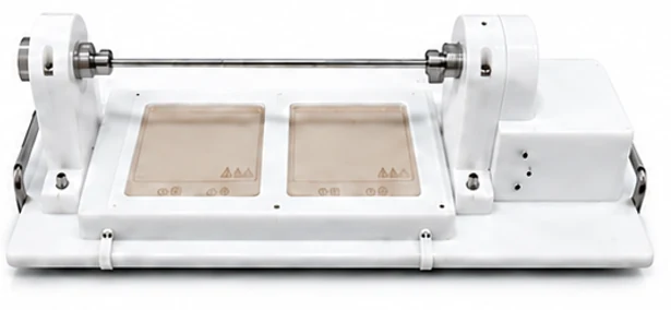
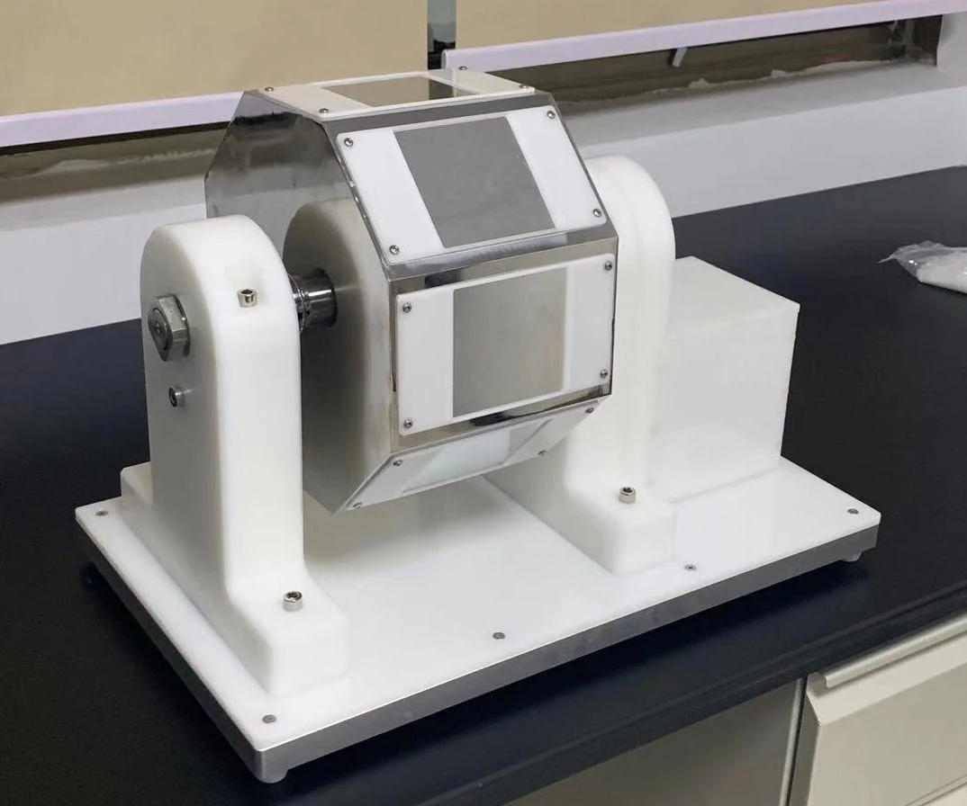
Rotating mandrel collectorEnlarge image ↗
Rotating mandrel collector
Tubular membrane sampleEnlarge image ↗
Tubular membrane sample

Rotating mandrel collector

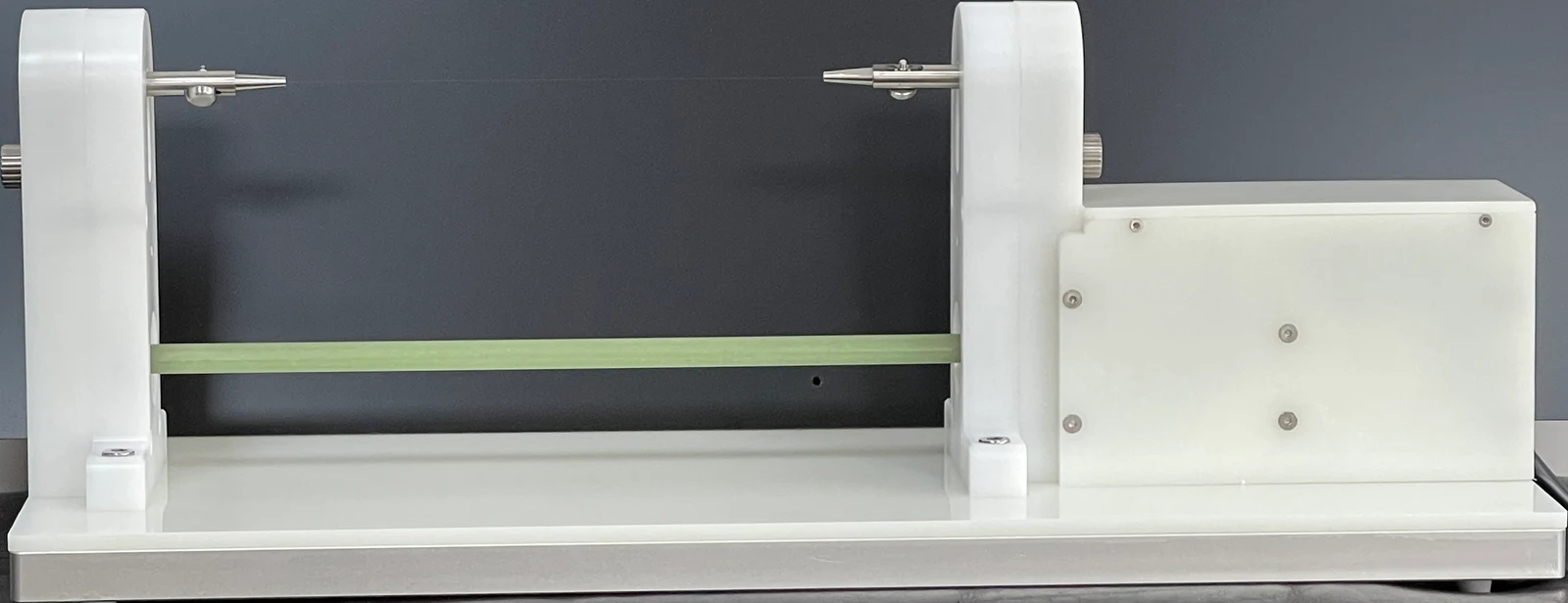
  • Produce hollow tubular membranes in different diameters for vascular graft and tubular scaffold research.
Mandrel diameter1–30 mm
Length300 mm
Tube wall thickness1 µm to several mm
Fiber diameter100 nm to several µm
Parallel-electrode cage collectorEnlarge image ↗
Parallel-electrode cage collector

Parallel-electrode cage collector

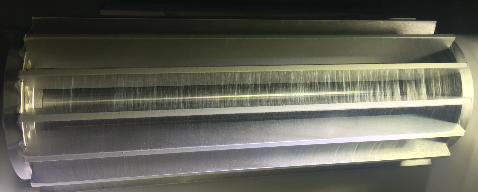
  • Parallel electrodes collect aligned nanofibers at low rotation speeds, with easy transfer to other substrates. Thick mats remain flat and uniform after unwrapping.
Drum diameter × lengthØ110 × 300 mm
Rotation speed1–150 rpm
Speed accuracy±1 rpm
Roll-to-roll collectionEnlarge image ↗
Roll-to-roll collection
Roll-to-roll collectionEnlarge image ↗
Roll-to-roll collection

Roll-to-roll collection

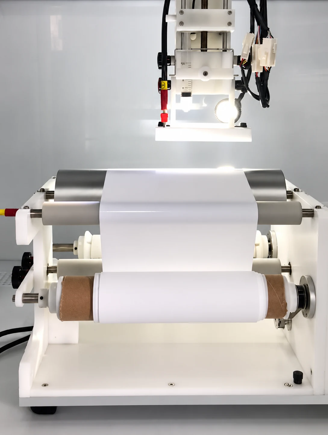
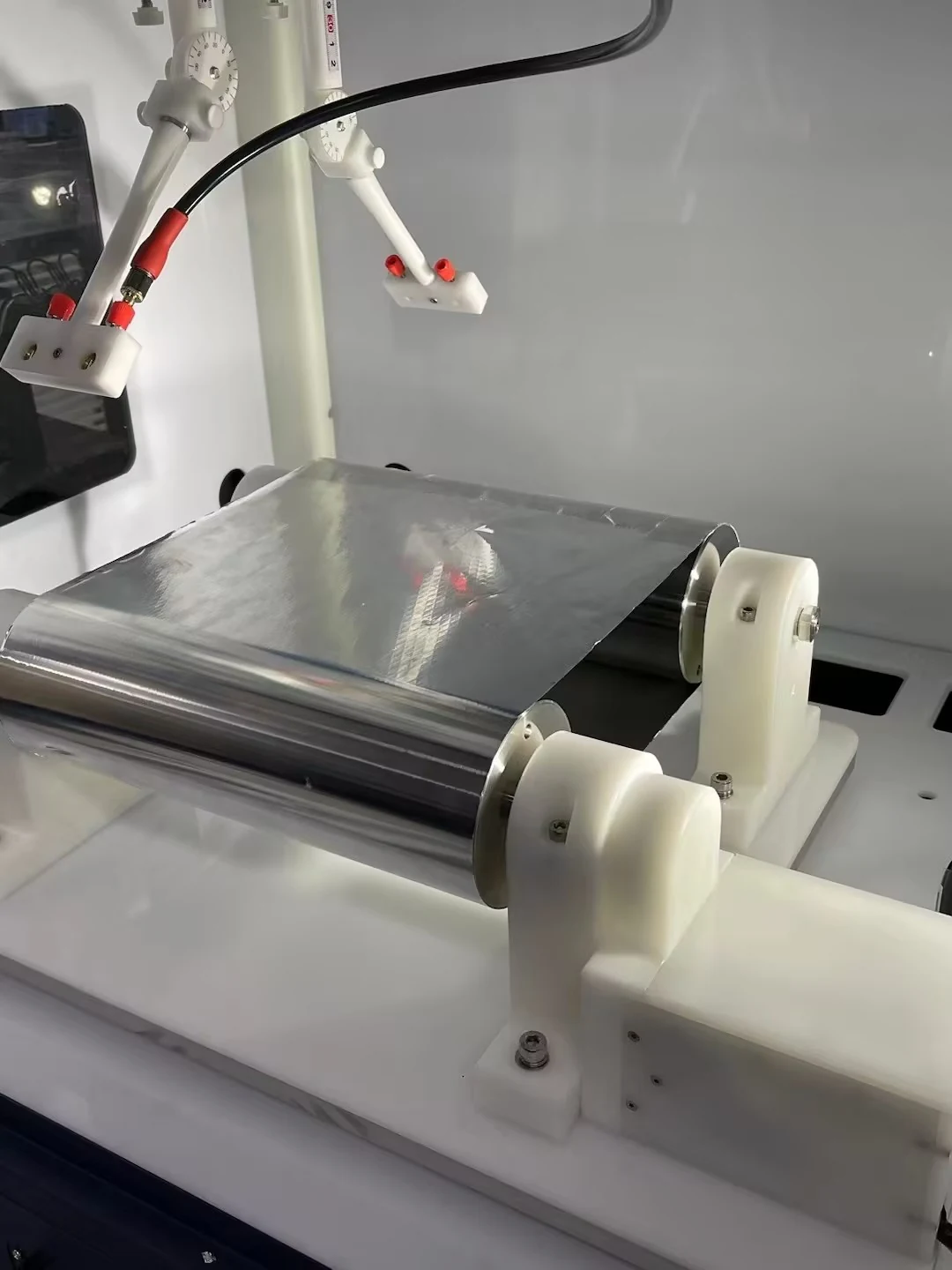
  • Collect nanofiber membranes continuously. Adjust take-up speed to the required membrane thickness, or select the fixed-length version.
Collection width250 mm
Maximum reel diameter65 mm
Continuous length50–100 m
Linear speed1–40 mm/s
Fixed-length versionApprox. 800 mm
Adjustable flat plate collectorEnlarge image ↗
Adjustable flat plate collector

Adjustable flat plate collector

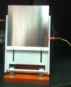
  • An adjustable-angle stainless-steel plate supports rigid substrates that cannot be rolled. An X–Y motion stage can be added as an option.
Plate size150 × 150 mm
Material316 stainless steel
05

Process options

Extend the platform with application-specific modules for heated spinning, continuous collection, yarns, three-dimensional mats and other deposition processes.

Heated spinneretEnlarge image ↗
Heated spinneret

Optional configuration

Heated spinneret

  • A 5 mL glass syringe supports small solution volumes for heated electrospinning and melt electrowriting, with positive high-voltage compatibility.
Spinneret temperatureAmbient to 150°C
Positive high voltage≤25 kV
Syringe5 mL glass syringe
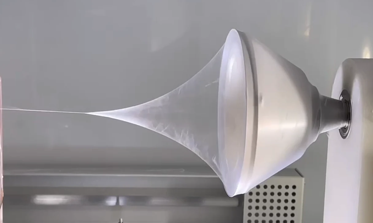
Spiral yarn collectionEnlarge image ↗
Spiral yarn collection
Yarn structure — SEMEnlarge image ↗
Yarn structure — SEM

Optional configuration

Spiral yarn collection

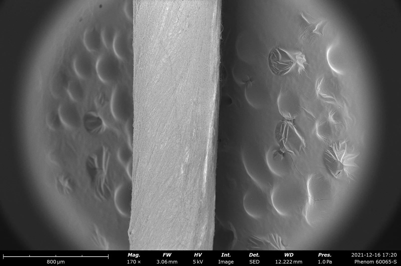
  • Produce continuous nanofiber yarns with or without a core. Core yarns receive a nanofiber coating; coreless yarns gather fibers into a continuous strand without a supporting core.
Thick mat sampleEnlarge image ↗
Thick mat sample
Thick mat sampleEnlarge image ↗
Thick mat sample

Optional configuration

Thick three-dimensional mats

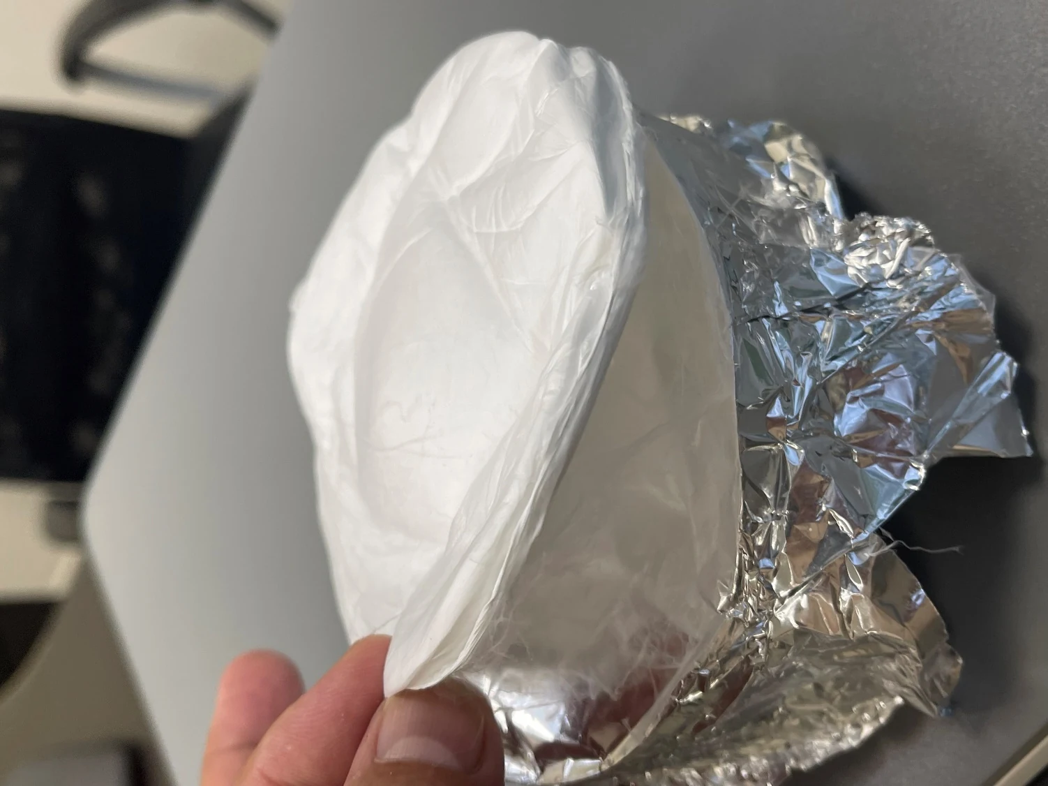
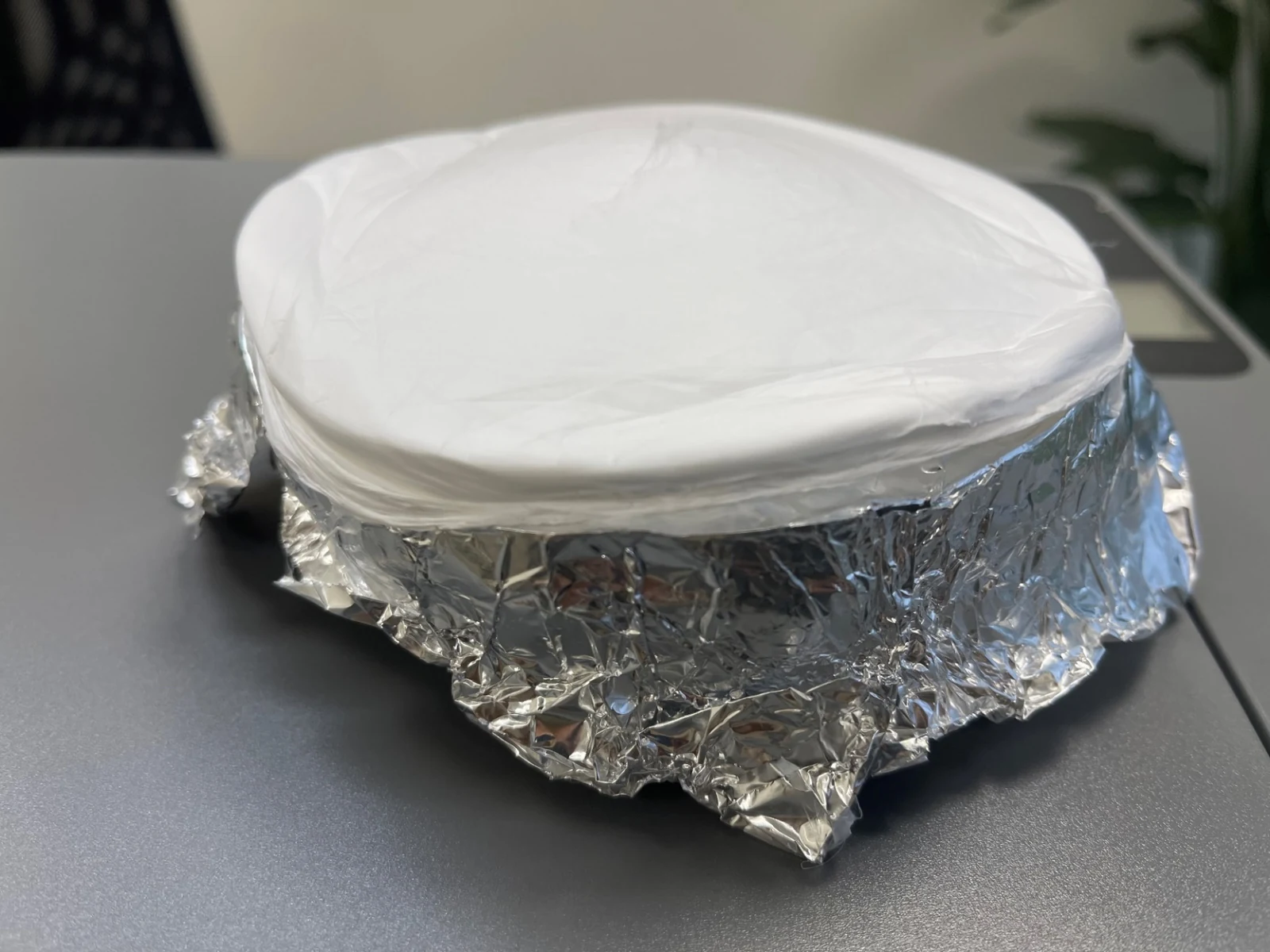
  • Continuously build a porous three-dimensional fiber network. Collection time and process settings determine thickness. Applications include filtration, adsorption, electrodes and tissue-scaffold research.
Nanoparticle and microsphere moduleEnlarge image ↗
Nanoparticle and microsphere module

Optional configuration

Nanoparticle and microsphere module

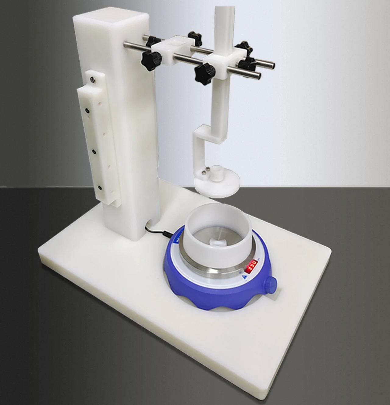
  • Collect dispersed nanospheres, short fibers and related structures in a liquid bath. The module includes a magnetic stirrer, insulating base, microsphere nozzle and holder, and auxiliary electrode.
  • Two bath vessels are supplied, one of each diameter.
Bath vessel diametersØ130 mm / Ø180 mm
Vessel height55 mm
Microwire coating collectorEnlarge image ↗
Microwire coating collector

Optional configuration

Microwire coating collector

  • Deposit nanofiber coatings on fine wires. Two motors control translation and rotation, with an independent controller and stepless speed adjustment.
Wire diameter10–1000 µm
Rotation speed1–5000 rpm
Speed accuracy±1 rpm
Fiber morphology — SEMEnlarge image ↗
Fiber morphology — SEM
Lofted fiber structureEnlarge image ↗
Lofted fiber structure

Optional configuration

Gas-assisted spinning

  • Aerodynamic and electrostatic forces work together to draw the jet. Throughput can reach approximately 20 times that of conventional electrospinning, depending on the material and process.
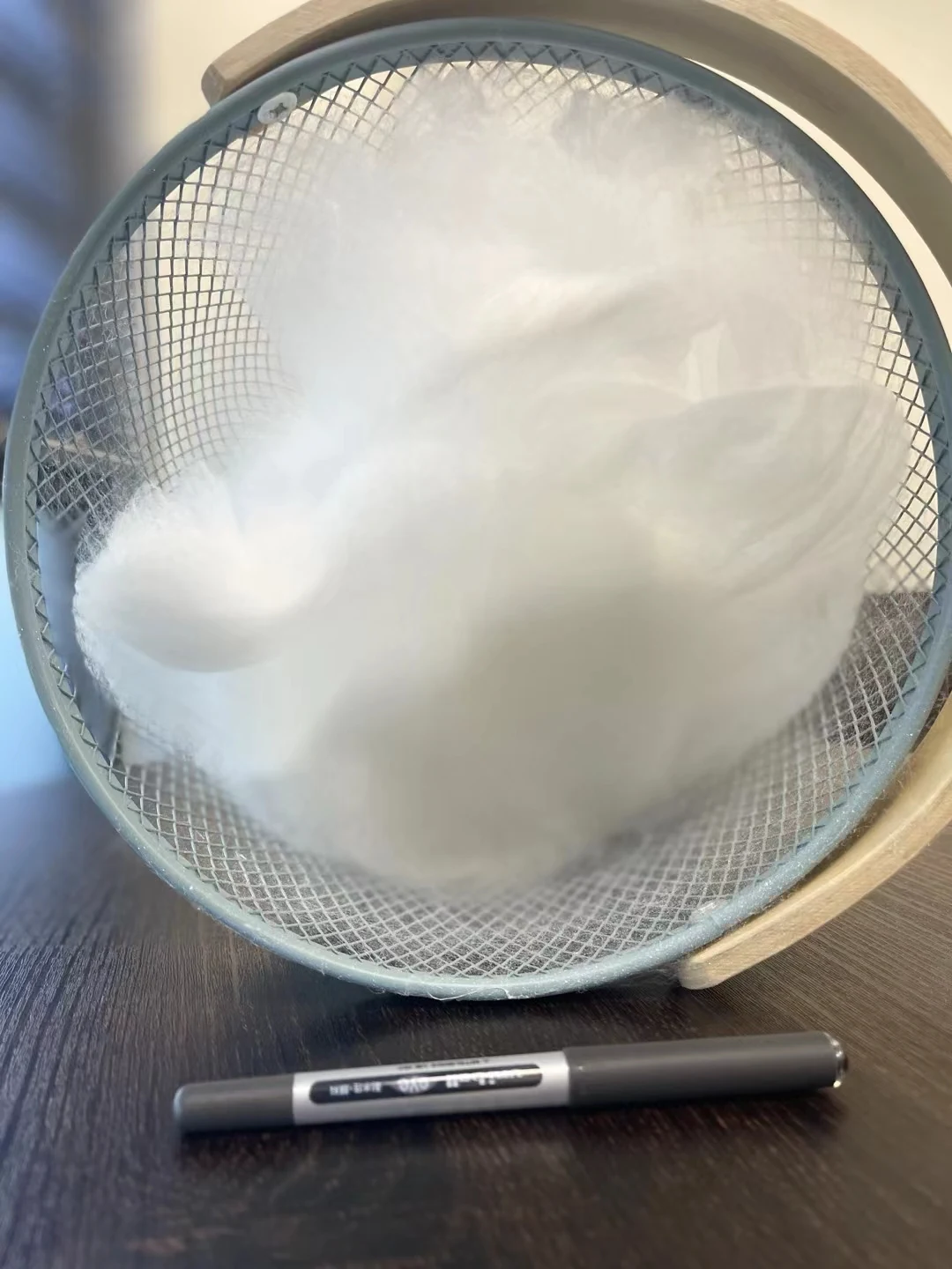
  • Supports straighter fibers with cleaner surfaces, membranes, lofted mats, cotton-like 3D structures and short fibers.
Dual-disc collection systemEnlarge image ↗
Dual-disc collection system
Cross-aligned membraneEnlarge image ↗
Cross-aligned membrane
Cross-aligned fibers — SEMEnlarge image ↗
Cross-aligned fibers — SEM

Optional configuration

Cross-aligned fiber module

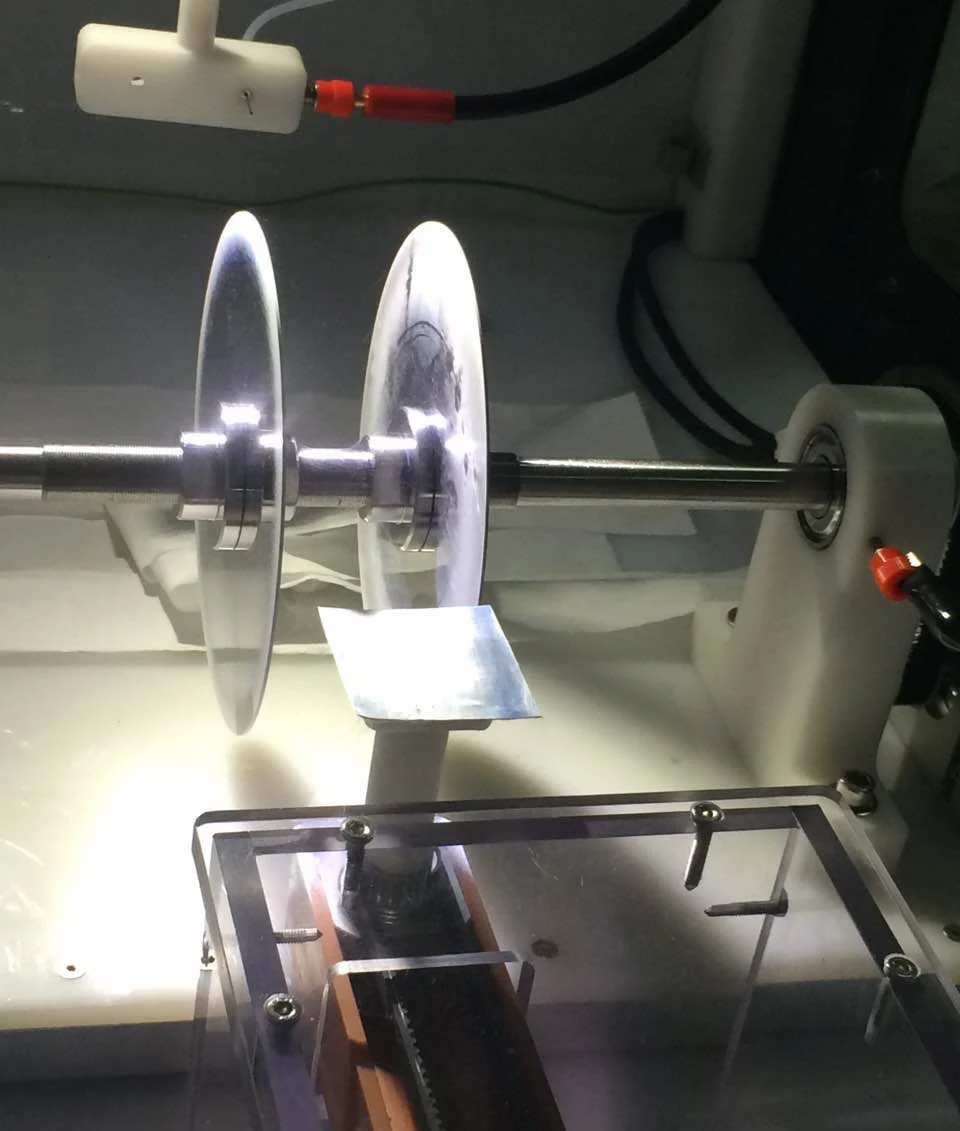
  • Build multilayer membranes with parallel or orthogonal fiber alignment. A dedicated spinneret, rotating dual-disc collector and independent digital controller support setup and process control.
In-situ UV curingEnlarge image ↗
In-situ UV curing

Optional configuration

In-situ UV curing

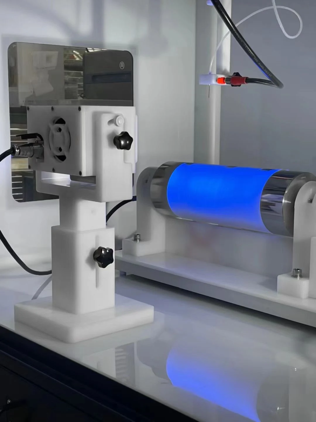
  • Automatic curing with uniform irradiation, without removing the sample for a separate post-treatment step. This reduces sample transfers and handling.
Peak wavelength365 nm
Emitting area30 × 25 mm × 2
UV irradiance≥420 mW/cm²
Lamp / installed power240 W / 290 W
CoolingAir cooling
Centrifugal electrospinningEnlarge image ↗
Centrifugal electrospinning

Optional configuration

Centrifugal electrospinning

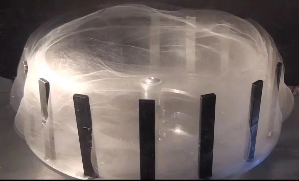
  • Centrifugal and electrostatic forces stretch and eject the polymer solution to form fibers with nanoscale or submicron diameters.
Spinning disc diameter650 mm
Rotating flat plate collectorEnlarge image ↗
Rotating flat plate collector

Optional configuration

Rotating flat plate collector

  • Servo-controlled rotation collects random or aligned membranes, including highly aligned fibers. The plate angle can be customized for the application.
Rotation speed1–5000 rpm
Plate size80 × 80 × 0.5 mm
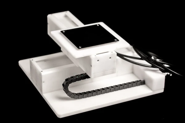
X–Y motion stageEnlarge image ↗
X–Y motion stage

Optional configuration

X–Y motion stage

  • Control two-dimensional paths on a flat plate collector with CAD import or programmed input. Includes a handheld controller and control box, timing-belt transmission and stepper motors, with insulating plastic construction.
X × Y travel200 × 200 mm
Positioning repeatability<50 µm
Linear speed0–30 mm/s
Power supply220 V, 50/60 Hz
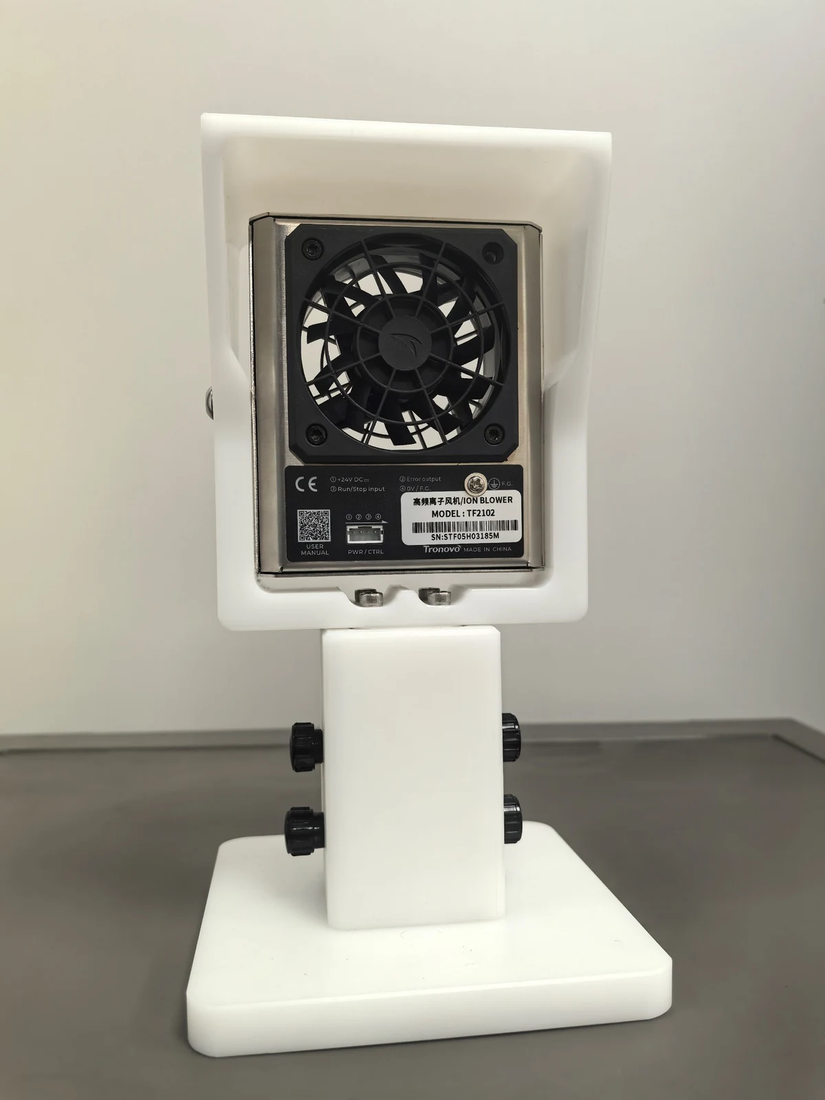
Ionizing air blowerEnlarge image ↗
Ionizing air blower

Optional configuration

Ionizing air blower

  • Neutralize static charge to reduce fiber adhesion and buildup. Controlled airflow supports more uniform deposition with fewer defects.
  • Also assists solvent evaporation, humidity regulation and process stability.
06

Safety, dimensions & downloads

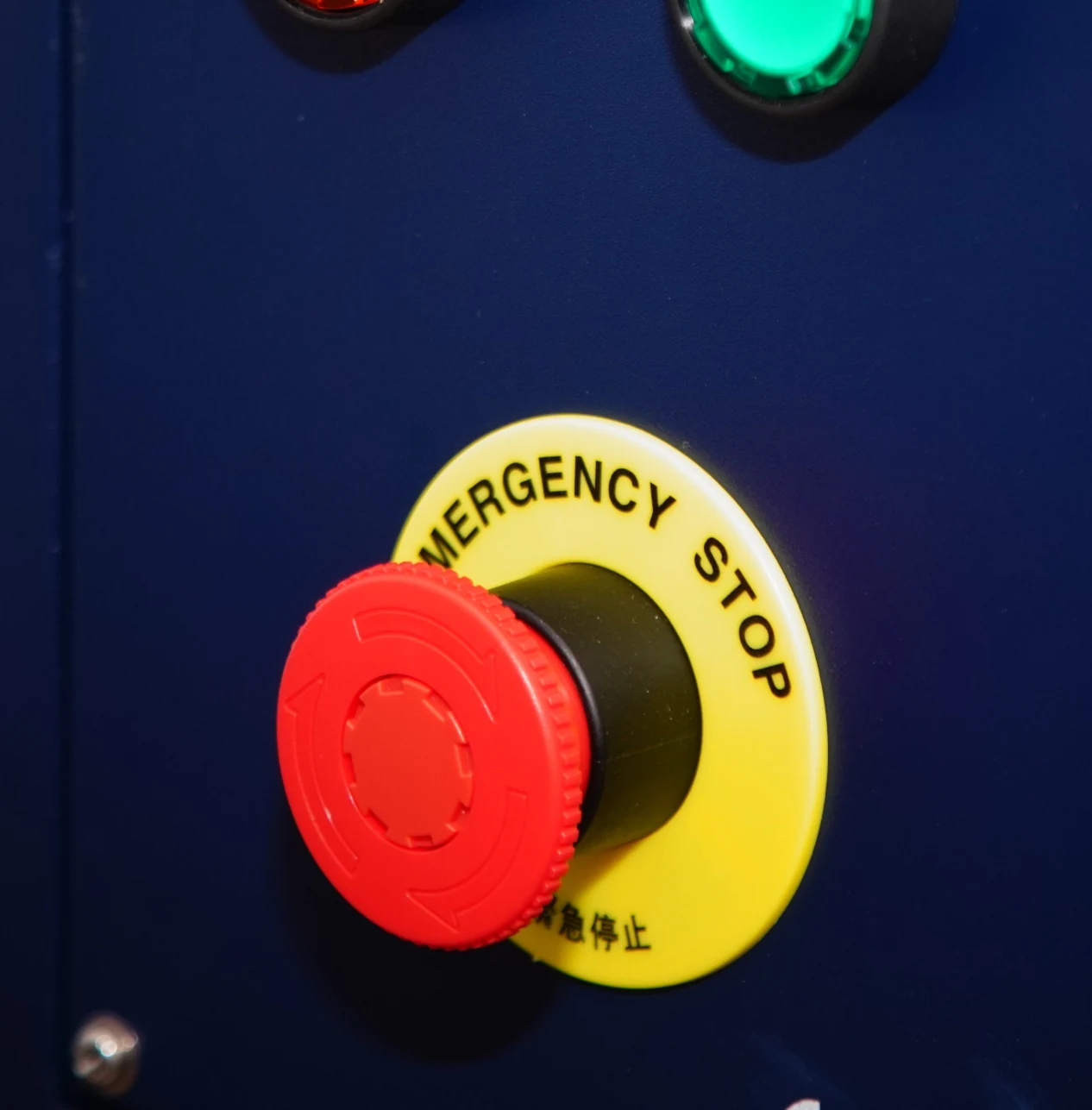
Emergency stopEnlarge image ↗
Emergency stop
High-voltage power protectionEnlarge image ↗
High-voltage power protection
Door interlockEnlarge image ↗
Door interlock

Operator and equipment safeguards

  • An accessible emergency stop enables rapid shutdown. Automatic power protection cuts off overvoltage and overcurrent.
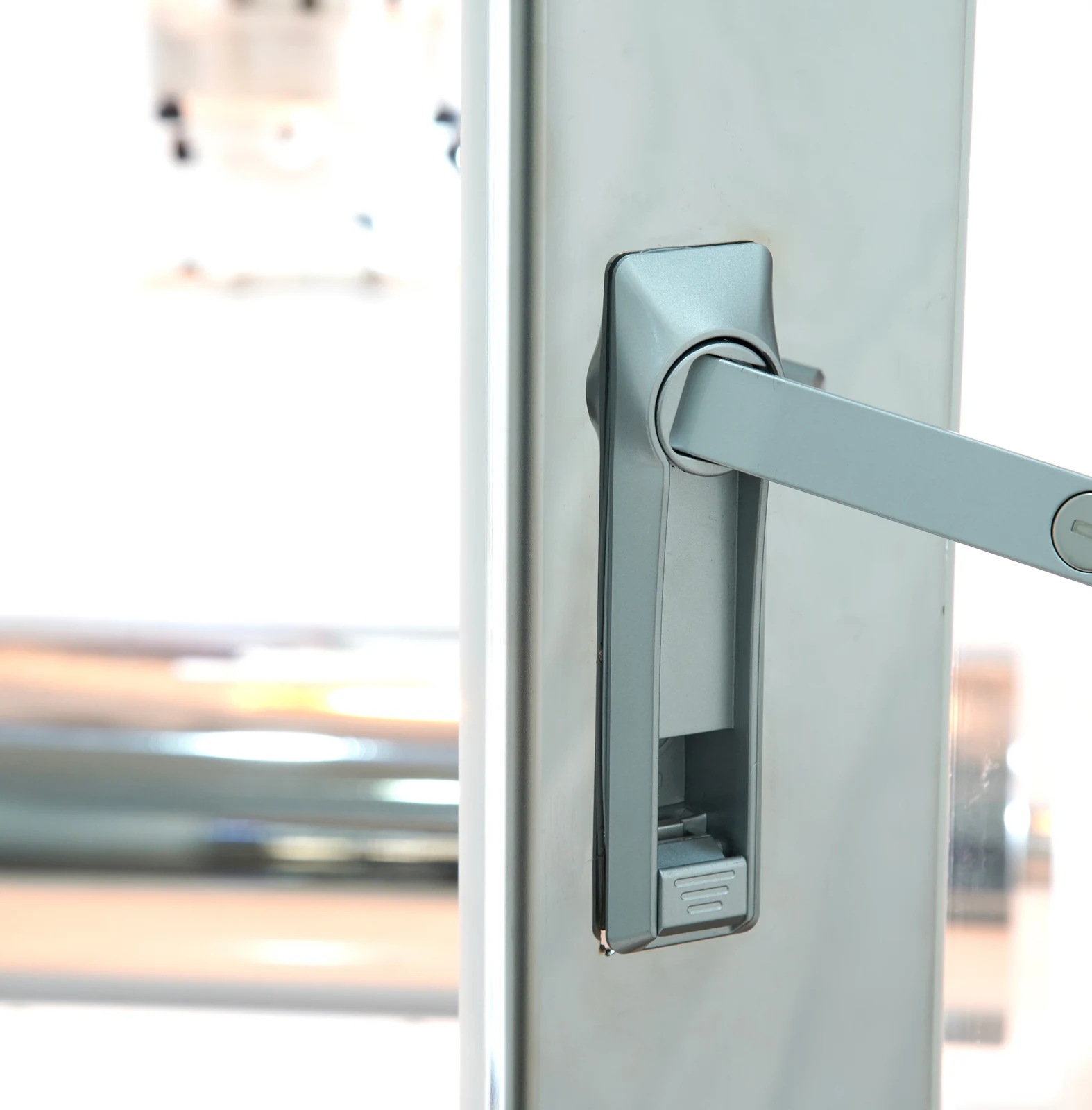
  • The door interlock shuts off high voltage when the door opens. Multi-point grounding connects the enclosure, high-voltage supplies, pumps and collectors.
System dimensionsEnlarge image ↗
System dimensions

System dimensions

  • The drawing shows the enclosure and the full installation envelope. Overall height includes the upper equipment assembly.
Enclosure, W × D × H1100 × 730 × 950 mm
Overall height1403 mm

Service & support

Three-year warranty with lifetime maintenance and after-sales support.

PDF · ENGLISH

TL-Ultra product brochure

English product brochure with equipment details, spinneret and collector options, technical data and dimensional drawings.

Download brochure (PDF, English)
Research & institutional records

Research involving TL-ULTRA

Institutional records and research papers connected through explicitly identified equipment models.

Only selected links found publicly on customer websites are listed here. Information without customer consent has not been disclosed.

The following sources identify TL-Pro-BM, the historical model corresponding to today’s TL-ULTRA. The original model name is retained for comparison with the source.


Independent Institutional Evidence

Published Research Using TL-Pro-BM

Institution-hosted research

Explore all research records for TL-ULTRA →

Tell us what you want to make.

Share your material, target structure and sample size. We can discuss a suitable platform and configuration.

Discuss your application